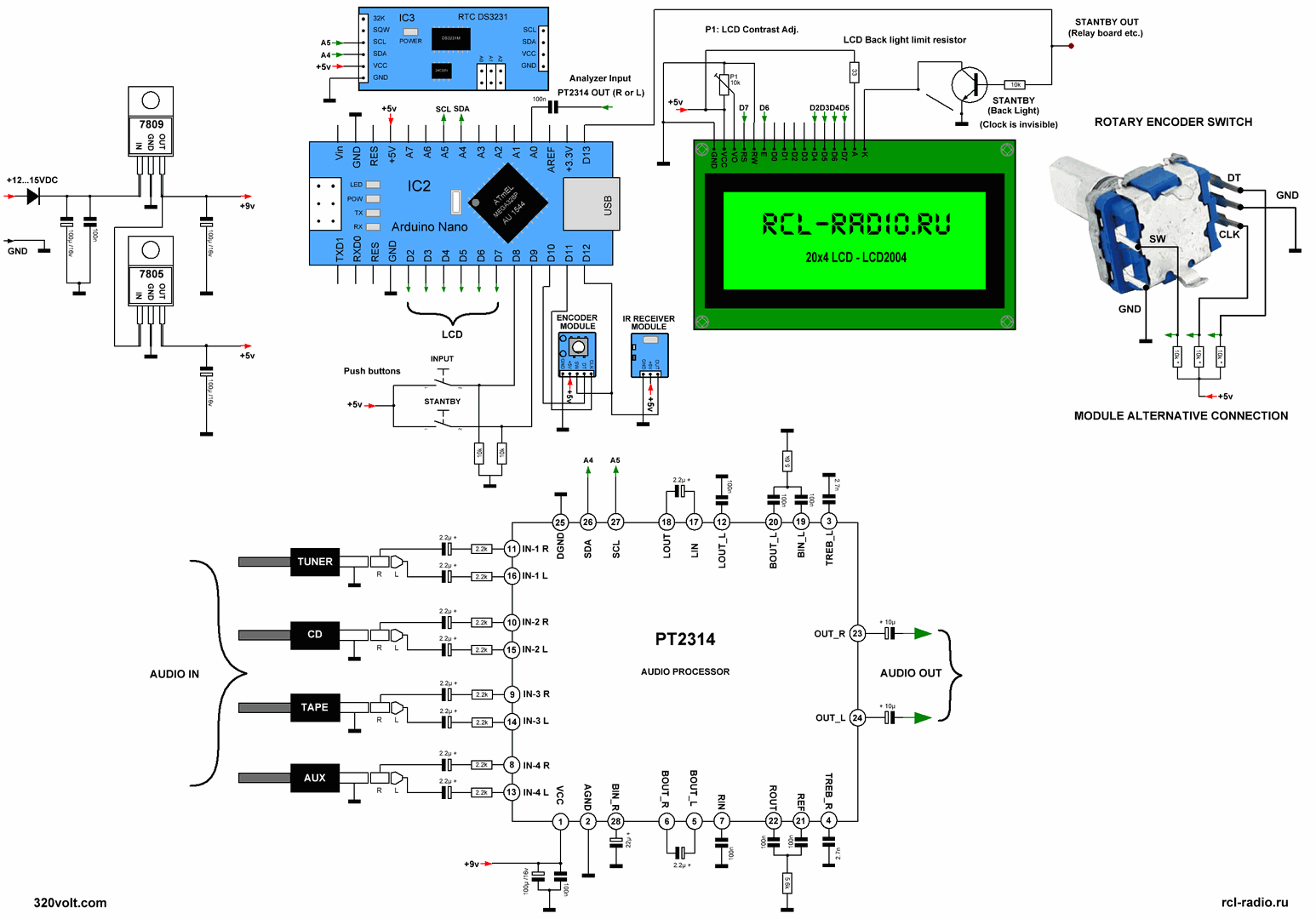
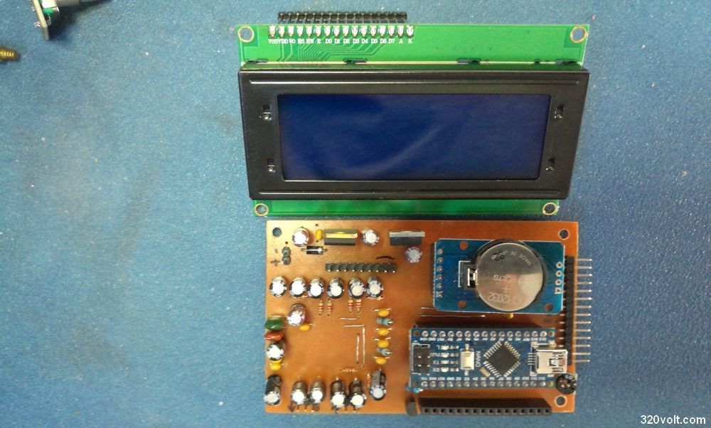
The PT2314 is a sound processor with a 4-channel stereo input selector, adjustable gain, volume control, frequency loudness compensation and tone control. I implemented the Arduino nano PT2314 project, it works pretty well. 2X20 LCD (LCD2004) is used for the display. 2 buttons are used for input selection mute, standby mode. Menu transitions and other settings are made with a keyed encoder.
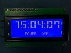
DS3231 module is used for time display, large font clock is displayed in standby mode. Another nice feature is that it is an LCD Spectrum Analyzer, the menu screen leaves its place to the spectrum analyzer after a while, and the spectrum analyzer can be adjusted for the number of columns.
With the button and keyed encoder, all settings can be made via Arduino nano, in addition, it can be controlled with a remote control via IR receiver module connection. In order to adjust according to the control in your hand, the same arrangement will be made in the 5.1 Digital Audio Control Circuit Arduino Nano PT2322 PT2323 article. I added a 2SC945 transistor to the Arduino nano standby output.
In addition, you can connect a relay module to the standby output and turn off the amplifier supply, or different scenarios can be applied (Relay and Relay Circuits) … All details in the video
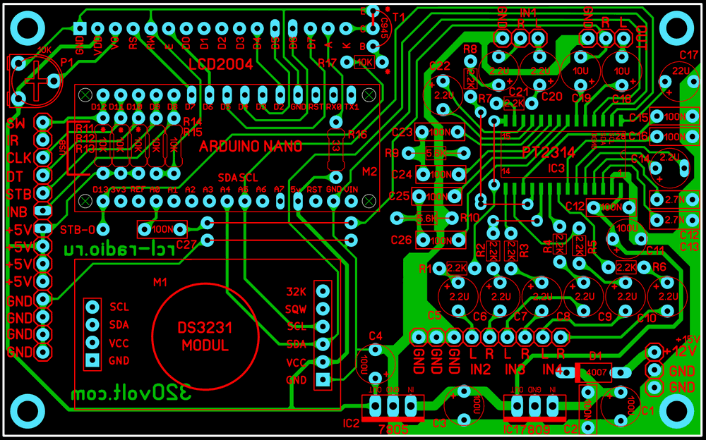
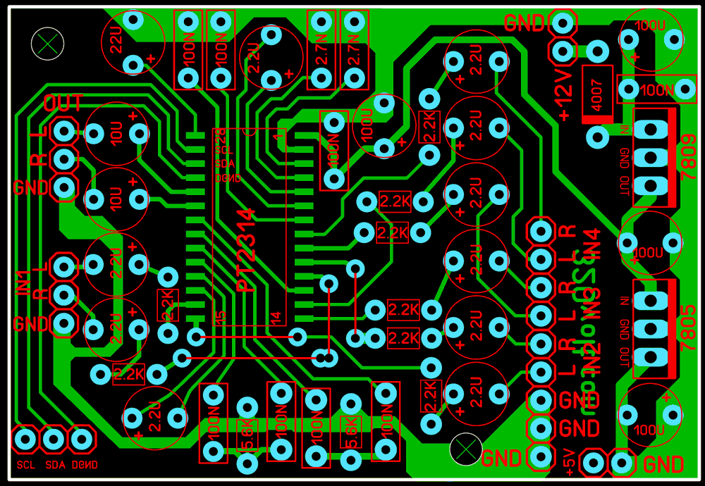
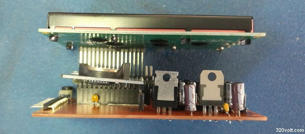
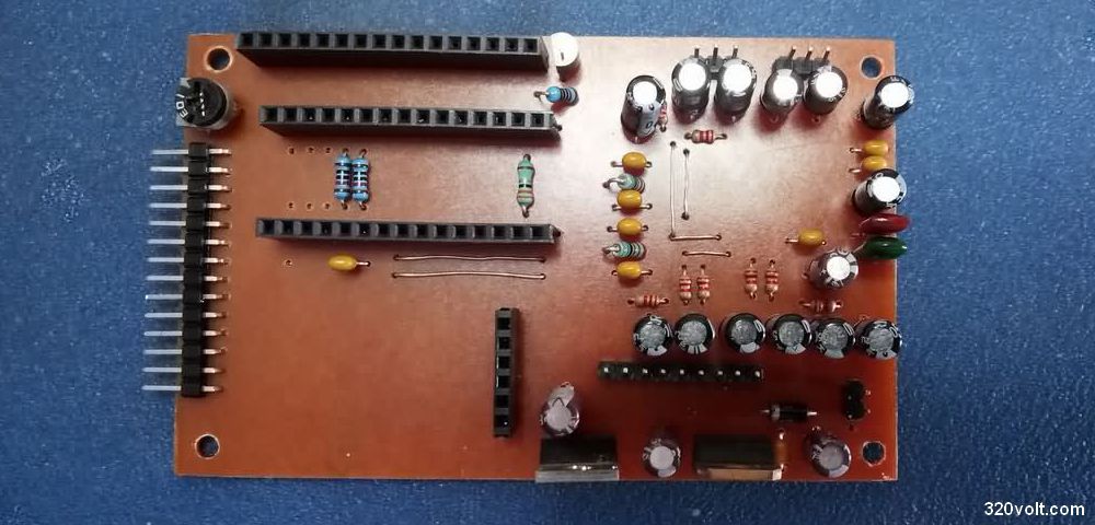
I made the PCB Drawing with Sprint Layout 6, the dimensions are the same as the 2X20 LCD, 100x60mm and in addition to the single layer, there are separate PCB drawings for the PT2314.
Arduino PT2314 Youtube
Arduino PT2314 Circuit Diagram PCB
About PT2314
The PT2314 is a four-channel internal input selector digital audio processor using CMOS Technology. Volume, Bass, Treble and Balance can be adjusted. Loudness Function and Selectable Input Gain are highly effective with the highest performance. All functions can be programmed using the I2C Bus.
• CMOS Technology
• Few External Components
• Treble and Bass Control
• Volume Control
• 4 Stereo Inputs with Selectable Input Gain
• Input/Output for External Noise Reduction System/Equalizer
• 2 Independent Controls for Stability Control
• Independent Mute Function
• Volume Control at 1.25 dB/step
• Low Distortion
• Low Noise and DC Stepping
• Controlled by I2C Bus Microprocessor Interface
Source: rcl-radio.ru/?p=76005


Hello Friend! Chiedo cortesemente il tuo aiuto come devo modificare il tuo sketch che hai creato per audio spectrum . probabilmente il mio progetto devo usare MCUFRIEND_kvb.h TFT LCD Shield 3.5 OPEN-SMART, pt2314,DS1302, Si4703 , IR Sir i Hope you can help me to solve It thank you
https://ibb.co/Kzmv3Qr
https://ibb.co/mS10WP5
Hello, this is a big change. Sorry i can’t help.
Excuse me. I make circuit based on your instruction but currently, ATmega328p can’t connect and control PT2314. I ran the I2Cscanner example but it only detects the 0x68 address of the DS1307. I also checked the I2C bus.Do you have any suggestions?
Hi,
Circuit is working 100% check everything.
After compiling sketch nothing is working, what mistake I am doing please help
Project is not working, I have uploaded the sketch but nothing works
hello the project is 100% working. check your circuit, use the libraries inside the file (do not update the libraries)
Hello! Arduino PT2314 PCB, code library files: 28606a.rar is wrong! We can not open!
hello install winrar latest version; https://www.rarlab.com/download.htm
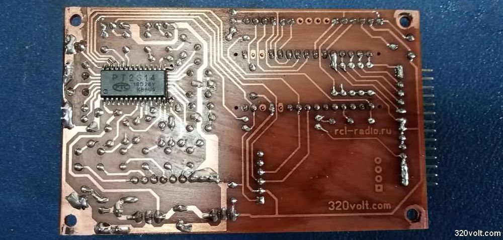
En la imagen de pcb donde fuguran los reguladores de tensión, en el circuito del LM7805 pin GND y el pin OUT están puenteados. Siendo así, el resultado es un bloqueo de ese regulador, un bloqueo de esa tensión y por ende nada funcionaría. No descargué sus archivos pero si el error reflejado en la imagen es lo mismo que se encuantra en los diagramas a imprimir, todos los usuarios tienen un cortocircuito en 5vcc. Saludos
Hello, No errors checked.
Obama is right. On pcb “PT2314-SOP28-DIP” there is short circuit on out and gnd pin of 7805. Just check and correct that!
👍
PCB file updated