Tag: smps projects

SMPS Circuits, SMPS Projects SMPS stands out, Switch Mode Power Supply There are basically 3 types of buck converter, boost converter and lowering-amplifier converter.

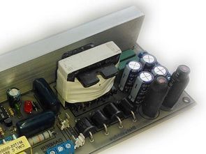
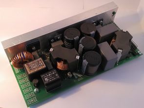
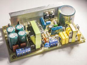
0.2V-80V 0-10A Adjustable Switched Mode Power Supply

| 2020/07/02

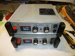
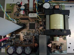
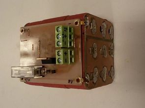
The 0.2V-80V switched power supply built on TL494 Integration can be used in various devices, motors, battery, battery charging processes, etc. designed for. There is additional SMPS circuit with TNY267 integrated circuit for feeding elements such as TL494, Fan, Relay. Like many circuit elements used in the SMPS Project, this material was supplied from PC…

IR2153 Audio SMPS Circuits

| 2020/07/02

SMPS designs designed as IR2153 amplifier power source based on IR2153 Integration. The 300W version gives 2X44V DC. Circuits have Short circuit protection. IR2153 SMPS 300W Version: In general, IR2153 Supply voltage is taken over 220v filter capacitor, that is, over + 310V resistor or mosfet regulator. In these circuits, 18k 2w resistor is connected…

SG3525 SMPS Laboratory Switching Power Supply 0-30 V 0-5 A

| 2020/04/27

SG3525 Adjustable SMPS 0-30V 0-5A Laboratory Switching Power Supply The SG3525A circuit was selected as the PWM modulator for controlling the switching power supply. It is a PWM modulator specially designed for control of switching power supplies. It has it two complementary outputs of the PWM signal, alternating one output can only range from 0…

UC3843 UC3845 Welding Inverter Circuit LiFePO4 Powered

| 2020/04/27

UC3845 LiFePO4 switch mode power supply charger. In order to simplify the connection, reduce the number of components and reduce the expected sources of problems, the following sections have been omitted around the UC3843 circuit. On pin number 2, overcurrent protection UC3843, a peak detector formed was launched components D10, C30 and R30 and pin…

300W LLC Resonant Switch Mode Power Supply SMPS

| 2020/04/26

LLC Resonant SMPS circuit 2X150W Amplifier circuit designed for power supply Circuit IRS27952 DC DC Resonant converter integrated on the circuit can supply 200W continuously 300W as peak (approx. there is. Efficiency of the power supply: between 92..94%. All information about the LLC Resonant SMPS project is given, transformer winding information, sprint layout pcb drawing.…

Salvaging ferrite cores with Hot Air

| 2020/02/06

Method: Salvaging ferrite cores Why The world is full of electronics being unceremoniously discarded. Said electronics contains power supplies. Said power supplies contain a number of magnetics, namely transformers and chokes with ferrite cores, of all sorts of sizes and shapes (well, usually E or EI, but anyway). A computer power supply will have several.…

Laboratory Power Supply 10A 2X40V L6562 PFC TMS320F28062 SMPS

| 2019/07/14

Smps circuit controlled by TMS320F28062 IR4427 Gate driver. Designed with pfc circuit L6562 The design of printed circuit boards and the creation of electrical schemes is realized through Eagle cad. Due to the design of the resulting device, the inlet filter is together with an active rectifier placed on a separate printed circuit board. On…

600W LED Dimmer Circuit PFC ICE2PCS01 UCC28C43

| 2019/07/09

This block is used to reduce and stabilize the voltage produced by the PFC block. The output voltage of this block is controlled by the control signal. Since the output voltage is higher than the safe touch (according to the CSN standard), it is possible to use the lower switch at the lowering drive. UCC28C43…

IR2161 SMPS Circuit IR2153 Alternative

| 2018/06/10

I’ve shared a lot of SMPS power supply projects with IR2153, especially AT, ATX power supply. The IR2153 works great for evaluating power transformers. Even bigger companies such as Yamaha have used the 8 pin MOSFET driver integration in their products. an integrated but not very common use in DIY environment I did not have…

14.4V Li-ion Battery Pack UC3844 SMPS Charger

| 2017/10/01

Li-ion 14.4V Battery Pack UC3844 SMPS Charger the UC3844 integrated circuit is supplied directly from the DC link via the resistor R2. After the circuit switches on, the power transistor Q1 is powered by the auxiliary winding. The RCD cell, consisting of R3, capacitor C3 and diode D1, protects the power transistor from positive overflows…