I shared many SMPS circuits made with IR2153. IR2153 is especially suitable for use in amplifier power supplies, even in power amplifiers in large companies, in mixers Power supply uses IR2153 on the SMPS floor. (Yamaha EMX5000 mixer service manual ir2153)
I have been working on the SMPS circuit I have applied for a long time, whenever I can, it was developed by utilizing the SMPS schemes of different devices. Overload, short circuit, long-term load (200W) tests were carried out. The power range of the SMPS Circuit can be expanded, depending on some material and transformer core, it can provide power between 100W…800W. You can use AT-ATX Power supply transformers to use it in low-power applications without dealing with SMPS transformer winding, as I did. PC power supplies also have transformers of different powers.
EI28 – 80W…100W
EI33 – 180W…250W
ERL35 – 250…300W
It can give strength (according to my experience and guesses 🙂 ) max. The transformer needs to be cooled at the limits, although it depends on how long you use your amp at high power.. I will talk about the power issue at the end of the article. The fan cooling system in PC power supplies cools the transformer as well as the power transistors, output diodes. In fact, heating, efficiency, etc. It’s also about the operating frequency of the circuit..
I used the stereo LM3886 module in the tests. Instead of the speaker, the load resistors are connected. At the end of the video, there is a short audio test with the TDA7294 200W module. I don’t have a high-power speaker at the moment… I quickly touched on many details in the video..
Audio Amplifier SMPS Circuit Diagram
1. EMI filter and DC rectifier
2a, 2b. Additional winding and regulator stage that provides the supply voltage of the IR2153 IC
3. IR2153 Driver stage
4. Overcurrent detection, protection stage
5. Secondary, DC output stage
6. Additional 12v voltage output for cooling fan
Attention: In the diagram, the connections of the capacitors C5 and C6 are faulty The plus leg of the capacitor C6 – 10uf will be connected to the leg IR2153 8 and the minus is the con to the leg number 6 The capacitor C5 – 1nf is the same NO problem with PCB drawing


First of all, although there are no 100nf 275VAC capacitors in the 220V input, the circuit works smoothly, but these materials are within the possibilities required for the filter or you can not use them for testing, but resistors connected in parallel to the 10-ohm NTC and 220uf capacitors are required because IR2153 may fail in high power circuits instead of NTC in high power circuits. Start circuits or high current NTCs are used by connecting them in parallel.
My favorite part of the IR2153 IC was that the supply voltage could be provided with simple methods, usually by limiting it with a 5…10W resistor.. but this method produces a lot of heat and takes up space, so I made 4 turns of 0.30mm wire outside the transformer, about 20…23V DC after DC rectification. This voltage is reduced to around 16V with a transistor and a zener regulator.
The operating frequency of the SMPS circuit is around 37KHZ, and the IR2153 frequency is determined by the values of the R17 and C16 elements. It is better to have a higher frequency, but we cannot increase it much because we use a ready-made ATX transformer.
For the first test; Before assembling the transformer, IRF730 mosfets and IR2153 IC, measure the regulator stage. At the cathode of the 16v zener, a voltage of around 16v should appear on the 16.8V IR2153 pin 1. The 100K 2W resistor provides the necessary voltage for the start. If everything goes well, when you run the circuit after assembly, there should be a voltage between 18v…20v at the output of the F+ 100 ohm resistor.

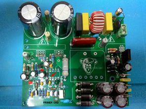
For IRF730 mosfets, as you can see in the pictures, a small heatsink is sufficient, they get very little hot.
According to the voltage drop on the 0.47 ohm 3W resistor in the overload, short-circuit protection layer, the T5 2N5551 transistor turns the protection layer to cut the IR2153 supply frequency.
The overcurrent protection circuit can be active at low powers according to the internal resistance of the transistors, hfe value and the tolerance of materials such as capacitors and resistors, and can switch to protection (or vice versa). In this case, you need to lower the value of the R15 5.6K resistor.
They say UF1010 instead of MUR160, HER107 diodes can be used. You can use more powerful TO220 sheath diodes instead of SR5100 5A 100V diodes on the secondary stage. PCB design was made accordingly
common anode diodes
MUR1620CTR
U12C20A
H16C20A
U16C20A
NTE6244
common cathode diodes
H16C20C
MUR1620
NTE6240
In the ATX transformer, I evaluated the 5V outputs for 12V fan supply, in addition, I added a fan control circuit with NTC sensor. You must short circuit it.
If you want the fan not to work at normal temperatures, you can use R35 resistance 20K…22K. With these values, the fan starts to work above 50 degrees, and if you want it to run slowly at normal temperature, you can use the resistance value between 33K…39K. It will be mounted on a 10K NTC amp cooler.
IR2153 SMPS circuit is ready Output from PC power supply With ERL35 transformer, it can give 2X30V 300W. For higher powers, high-voltage filter capacitors, mosfets, transformer, shunt resistor power and value input, output diodes, capacitor values must be changed in the file Harbinger, Titan service manuals it will give inspiration..
ExcellentIT SMPS Transformer calculation program will do your job for transformer calculation Let’s not forget the IR2153 frequency calculation program, all documents and programs are in the file.. The core of the transformer I use is a little small compared to EI33, in the tests I determined the most suitable oscillator resistance value as 18K. depending on the situation, but I had no problems in long-term tests.
Finally, don’t forget to cover the 47k 2w, 100k 2w, 100 ohm 2w and fuse with heat shrink tubing placed vertically, and insulation should be done in the cooler assembly of the mosfets. I say amp power supply, but it can be used in different projects, for example, you can get 30v by rectifying with 2 diodes on the secondary output stage, and you can use it for a regulated laboratory power supply. By using 2 Ready PC power supply transformers, more power can be obtained from transformer winding etc..
PCB design of IR2153 SMPS Circuit was prepared with Sprint layout 6 PCB dimensions 100X86mm


FILE DOWNLOAD LINK LIST (in TXT format or file): 27704a.zip pass: 320volt.com
Published: 2021/09/20 Tags: power electronic projects, smps circuits, smps projects, smps schematic
There is an error on the diagram. Connection C5 and C6 not correctly drawn.
Yes, the schema is wrong. PCB correct no problem. Thank you for feedback.
How to change the circuit to get 12v and 5v instead of 30 and 12