Mikropascal Mikrobasic MikroC Projects
Micro-Electronica product areas owned by the user that sent the company projects in various fields has many applications with source code in some simulations, there proteus isis. Mikropascal Micro C..
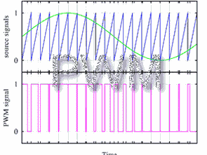
What PWM works How PWM Pulse width modulation is the technique of obtaining the analog electrical value or signal to be produced at the output by controlling the width of the pulses to be produced.
Micro-Electronica product areas owned by the user that sent the company projects in various fields has many applications with source code in some simulations, there proteus isis. Mikropascal Micro C..
CNC motor control card from the computer’s LPT port kullanılbiliy communication is made. Drivers at the unipolar stepper motor driver integrated Sanken SLA7062M used SLA7062M 3 amps of power has..
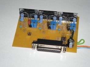
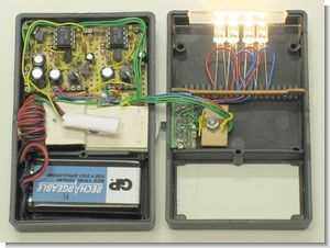
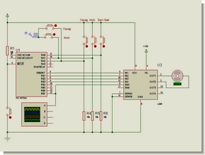
In this project depends porta.7 porta.6 and with the help of two buttons are applying PWM to the complete portB. Duty value can be changed with the help of buttons…
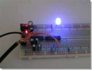
High Efficiency 0-100% LED Dimmer How to convert 10mA from your battery to 20mA for your LED? This webpage describes a high-efficiency LED dimmer or a dimmable LED flashlight, or..
Article, the project sent from sharing section of a dc motor control applications. Applications that perform, and that leads us to thank our readers @Hüseyin DEMİRBİLEK itself. I occasionally share..
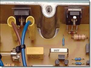
Working with 24 volt motor driver circuit motor bike used with modified by attaching the TL494 control integrated circuit MOSFET driver transistors have three different versions of the system used..
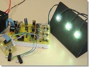
Power LED driver circuit based on Atmel ATmega8 is working with 12 volt 3 1 watt Luxeon power LEDs with PWM buck converter is operated ATmega-8 a good example source..
An interesting project computer-aided olmasıda a very good feature. Supervision can be said that the RGB PWM circuit PIC16F628 dali assembly prepared with software installed on the RGB data while..
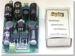
DC to DC converter circuit size and quite a lot of small passive components used PWM control TL494 SMD type Matchbox output coil in comparison with the size of the..
A very powerful speed control circuit, 1 FGA25N120 igbt is used in the power floor, there is also an overload protection section, the control is driven with igbt cd4050 based..