LiPo batteries are increasingly becoming a primary source of power, replacing other chemical sources of energy. The upgraded device, powered by a USB port or a mobile phone charger, allows you to charge medium capacity LiPo cells with critical operating life and operational safety. Compared to the previous one, it offers higher current charging (up to 1A) and full charge cycle signaling.
The MCP73833 charger IC has a built-in temperature sensor that limits the charging current in case of excessive system temperature. To facilitate the loss of power, it is advisable to use a small heat sink adhesive and use a power supply that provides a stable supply voltage of +5 V. MCP73833
Li-Po charger circuit schematic MCP73833
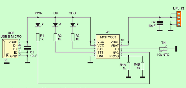
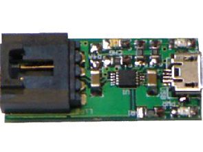
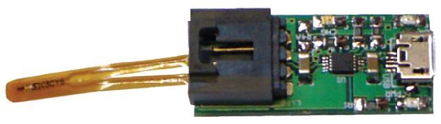
The MCP73833 charger is powered from the micro USB connector by +5 V. The system controls the temperature of the charged cells with a 10K NTC thermistor, limiting, if necessary, the charging current. LEDs indicate: PWR – presence of power, CHG – charge of the link, OK – completion of charging. The Lipo battery socket is used to attach the charged battery. This is typical of most cells, a 4-pin EH socket. Capacitors C1 and C2 filter the supply voltage.
![]()
FILE DOWNLOAD LINK LIST (in TXT format): LINKS-25811.zip


MCP73833 USB-betriebener Li-Po-Ladeschaltkreis
LiPo-Batterien werden zunehmend zu einer primären Energiequelle und ersetzen andere chemische Energiequellen. Das aufgerüstete Gerät, das über einen USB-Anschluss oder ein Ladegerät für Mobiltelefone mit Strom versorgt wird, ermöglicht das Laden von LiPo-Zellen mit mittlerer Kapazität mit kritischer Lebensdauer und Betriebssicherheit. Im Vergleich zum Vorgängermodell bietet er eine höhere Stromaufladung (bis zu 1 A) und eine vollständige Signalisierung des Ladezyklus.
Der Ladestecker MCP73833 verfügt über einen eingebauten Temperatursensor, der den Ladestrom bei zu hoher Systemtemperatur begrenzt. Um den Stromausfall zu erleichtern, empfiehlt es sich, einen kleinen Kühlkörperkleber zu verwenden und ein Netzteil zu verwenden, das eine stabile Versorgungsspannung von +5 V liefert. MCP73833
Li-Po Ladegerät Schaltung MCP73833