The charger presented in the article is intended for charging the battery pack – LiFePO4 2S 1.8Ah with electricity from a photovoltaic cell. The charger is based on a LTC3652HV integrated circuit which is a universal battery charger controller, adapted to be powered from a PV solar panel. Recommendations: the charger is worth taking with you on trips to the terrain, camping, etc.
As mentioned in the introduction, the charger is basically an application of a specialized integrated circuit LT3652HV, which has a built-in PV peak power peak tracking algorithm similar to MPPT.
Block diagram of the LT3652HV system is shown in Figure 2. The system includes a reduction converter with a wide input voltage range and a maximum load current of 2 A. The system is designed for charging batteries made in the most commonly used technologies: AGM, LiPo, LiFePo using the CV / CC algorithm, enabling the charging of packages with a voltage of up to 18 V. It has a built-in thermal protection circuit for the battery, a charging timer and circuits for signaling operating states.
Schematic Diagram of the LiFePo4 Charger
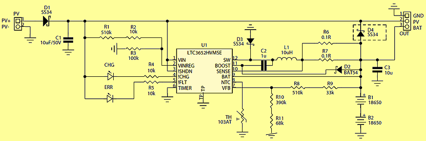
The prototype charger works with a typical, low voltage PV panel with a capacity of 10 … 20 W (eg MWG-20), with a voltage at the maximum power point of 17,5 V. The voltage from the cell has been connected to the PV connector. The Schottky D1 diode prevents the effects of reverse panel connection. The charger system works continuously, which forces a high level of input! SHDN. A resistor divider composed of resistors R1 … R3 defines the voltage threshold below which the current consumption from PV is reduced, which allows work in the vicinity of the maximum power point.
rys2 The principle of operation of the maximum power tracking system is simplified and assumes reducing the current loading the panel, when the voltage at its terminals is lower than the maximum power point, which causes an increase in voltage at the panel terminals and increasing the current consumption when the panel voltage exceeds the defined value (which causes a voltage drop on the panel terminals), forcing the charger to work around the maximum PV power point. The built-in VINREG input comparator has a fixed switching threshold of 2.7 V. For the given resistance values of the divider R1 … R3, the maximum power voltage is about 17.5 V and can be adapted to a specific PV model by changing the R2 value including the slope on D1. The charging current is defined in parallel connected resistors R6 and R7. Correction of the charging current for a particular type of battery is made according to the formula R6 || R7 = 0.1 / Ioad. In the model, the maximum charging current is 2A (R6 || R7 = 50 mV), which corresponds to 1C for the used battery.
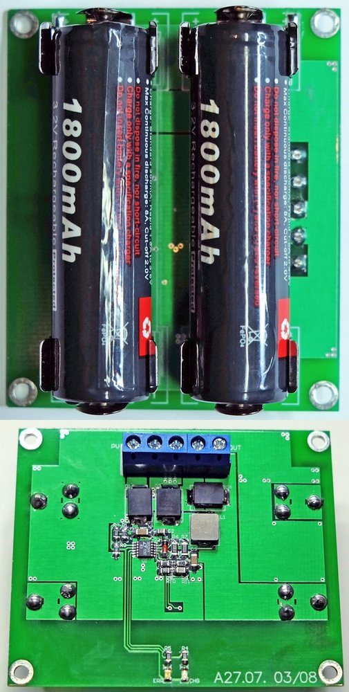
For energy storage, typical LiFePo4 batteries are used in the 18650 housing with a capacity of 1.8 Ah, with built-in PCB protection. In the case of a combination of batteries with small capacities in the 2S package, it is acceptable to abandon the cell balancing system, but it is worth using new links from reliable manufacturers, preferably from one production series, unless we can measure their actual capacity. The use of more expensive LiFePo batteries is dictated by their higher permissible number of charge cycles before a significant loss of capacity (as declared by the manufacturer above 1500 cycles). The divider connected to the Vfb input is responsible for the inverter output voltage equal to the charging voltage limit. Due to the need for very precise voltage determination (critical parameter for lithium batteries) and the desire to avoid the use of hard-to-acquire resistors, the divider consists of four resistors R8 … R11 with a tolerance of 1% and typical resistances. The TH thermistors placed in the vicinity of the accumulators protect them against charging when their temperature exceeds 40 ° C. Due to the unpredictable and dependent on the lighting conditions availability of power from the PV panel, the safety timer system is turned off, because the temporary power failure connected with the cloud would disturb its operation. The system for limiting the discharge current is still active when the battery reaches the charging voltage, which is sufficient protection.
![]()
FILE DOWNLOAD LINK LIST (in TXT format): LINKS-26095.zip


STK4241 STK4201 STK4221 STK4211 STK4231 Amplifier Circuit
STK4241 STK4201 STK4221 STK4211 STK4231 Amplifier Circuit
The amplifier uses a hybrid two-channel IC STK4241-II manufactured by SANYO. Immediately, it is worth noting that the pinout of the STK4241 is compatible with such chips as the STK4201V-series (THD = 0.08%) and the STK4141-series (THD = 0.02%). In the archive for download you will find 5 technical descriptions (DATASHEET) on STK4201, STK4211, STK4221, STK4231 and STK4241.
According to the Datasheet on STK4241-II, the recommended supply voltage is 2 x 54V DC, the load resistance is 8 ohms, the input impedance is 55 kΩ, the output power is 120 + 120 watts. We give the technical characteristics of the amplifier (data taken from the datasheet)
Schematic diagram STK4241
LTC3652 Chargeur de batterie solaire LiFePo4
Le chargeur présenté dans l’article est destiné à charger la batterie – LiFePO4 2S 1.8Ah avec l’électricité d’une cellule photovoltaïque. Le chargeur est basé sur un circuit intégré LTC3652HV qui est un contrôleur de chargeur de batterie universel, adapté pour être alimenté à partir d’un panneau solaire PV. Recommandations: le chargeur mérite d’être emporté avec vous lors de vos déplacements sur le terrain, en camping, etc.
Comme mentionné dans l’introduction, le chargeur est essentiellement une application d’un circuit intégré spécialisé LT3652HV, qui possède un algorithme de suivi de pic de puissance de crête PV similaire à MPPT.
Le schéma de principe du système LT3652HV est illustré à la figure 2. Le système comprend un convertisseur de réduction avec une large plage de tension d’entrée et un courant de charge maximal de 2 A. Le système est conçu pour charger des batteries fabriquées dans les technologies les plus couramment utilisées: AGM, LiPo, LiFePo utilisant l’algorithme CV / CC, permettant la charge de boîtiers avec une tension allant jusqu’à 18 V. Il a un circuit de protection thermique intégré pour la batterie, une minuterie de charge et des circuits pour signaler les états de fonctionnement.
Schéma de principe du chargeur LiFePo4