LM2576T-ADJ Power supply DC DC through long cables is associated with the voltage that is the greater, the longer the cable length and the current drawn by the receiver. Sometimes this fall is so big that the receiver is not working properly. The presented regulator compensates for this by measuring the voltage at the receiver and raising the output voltage accordingly if necessary. Recommendations: The LM2576T-ADJ regulator and the described method are the perfect base for building your own precise power sources.
The resistance of the power supply leads causes the current to flow into the voltage drop. This can be modeled as concentrated resistance. It may be that the length of the wires is so big that the receiver stops working properly. The easiest way to counteract this is to set a higher supply voltage on the power supply. However, if the current is changing, it may damage the receiver too high voltage.
LM2576T-ADJ Power supply circuit schematic
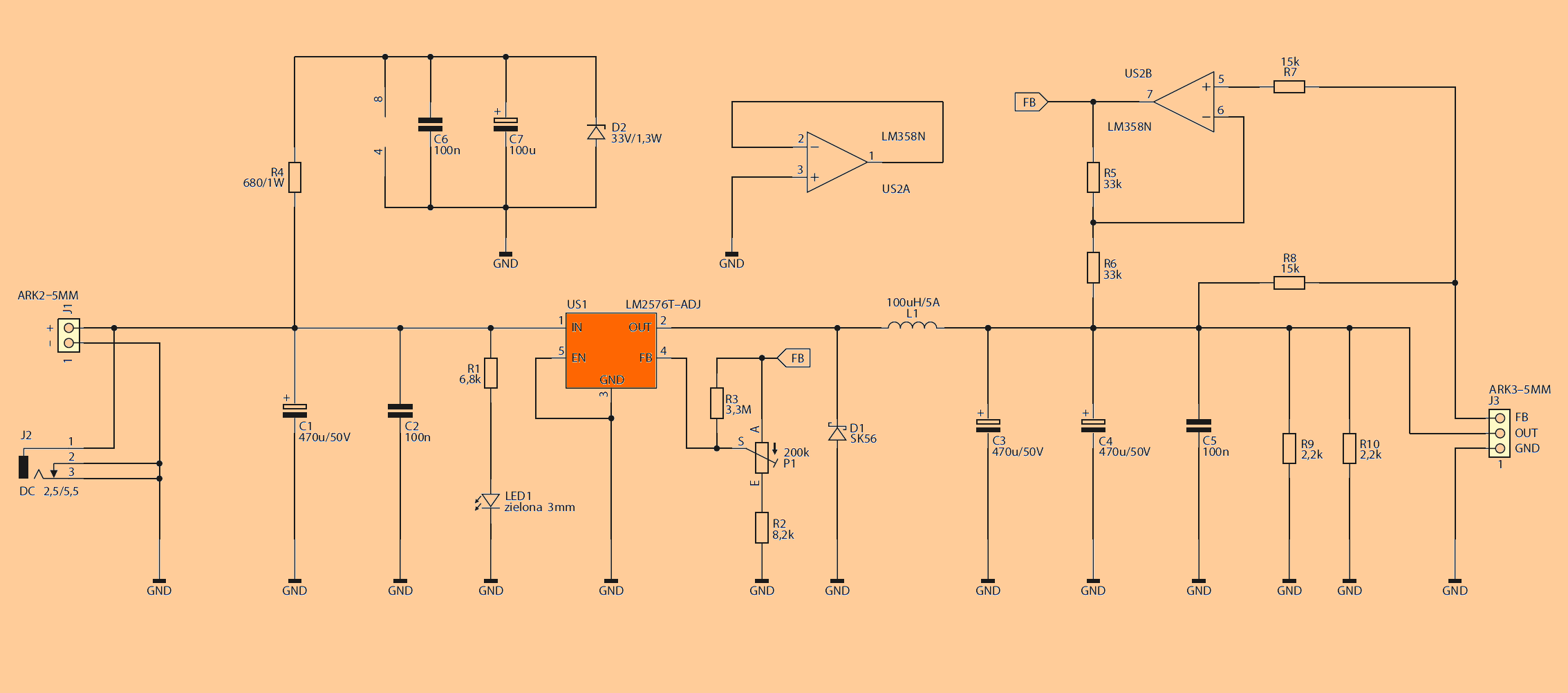
The Power supply circuit is shown in Figure 4. Its main unit is a step down regulator, based on the LM2576T-ADJ. The current efficiency of the stabilizer based on this system is up to 3 A, so it will be perfect for many applications. On the market you can find much more sophisticated systems with higher efficiency, but their use in this system would be very difficult, because in order to achieve high speed regulation, the feedback signal can not undergo any significant delay. Here the delay is entered by long connections and the amplifier, which has limited bandwidth. For this reason, the range of integrated impulse stabilizers that can be used in this arrangement is limited.
![]()
FILE DOWNLOAD LINK LIST (in TXT format): LINKS-25860.zip


LM2576-ADJ Einstellbarer Stromversorgungsschaltkreis
LM2576T-ADJ Stromversorgung DC DC durch lange Kabel ist mit der Spannung verbunden, die um so größer ist, je länger die Kabellänge und der vom Empfänger gezogene Strom sind. Manchmal ist dieser Fall so groß, dass der Empfänger nicht richtig funktioniert. Der vorgestellte Regler kompensiert dies, indem er die Spannung am Empfänger misst und bei Bedarf die Ausgangsspannung entsprechend erhöht. Empfehlungen: Der Regler LM2576T-ADJ und das beschriebene Verfahren sind die perfekte Grundlage für den Aufbau eigener präziser Stromquellen.
Der Widerstand der Stromzuführungen bewirkt, dass der Strom in den Spannungsabfall fließt. Dies kann als konzentrierter Widerstand modelliert werden. Es kann sein, dass die Länge der Drähte so groß ist, dass der Empfänger nicht mehr richtig funktioniert. Der einfachste Weg, dem entgegenzuwirken, ist eine höhere Versorgungsspannung am Netzteil einzustellen. Wenn sich der Strom jedoch ändert, kann der Empfänger zu hohe Spannungen verursachen.
LM2576T-ADJ Stromversorgungsschema
hi.
um Newly for 320, zip file ask password. pl help
Hi, pass: 320volt.com