The regulator circuit with mosfet has a simple structure and can provide 5v 3 amps at the output with 24v input voltage. The author warned that the input voltage should not be below 11v.
Switching regulator with 5V 3A mosfet Super simple regulator works very well but is it possible to improve it? Maybe with a mosfet transistor its features will improve.
In principle, it is necessary to check whether it is possible to obtain a sufficient voltage at the output of the first transistor to activate the mosfet gate in the previous design. By swapping a pair of resistors I can get enough voltage to activate a P-channel mosfet placed in place of the BD136. It improves overall performance as the ON resistance is very low and allows much higher output currents than a bipolar transistor.
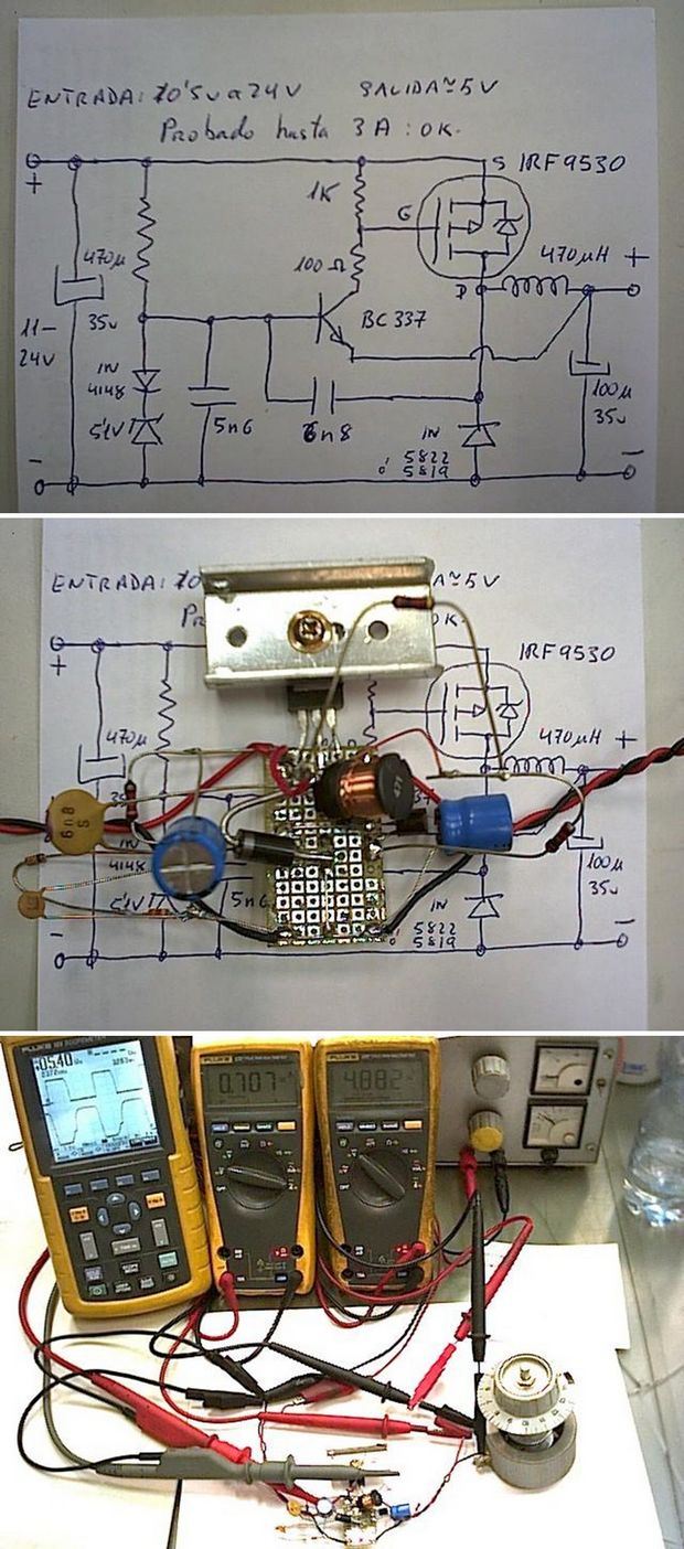
This is the schematic of the regulator adapted to use the mosfet:
By increasing the capacitor value from 2.2nF to 6.8nF, I lowered the switching frequency to about 25Khz. I get better results this way, although maybe the inductance of the output coil needs to be increased, I haven’t done tests on this. I did not measure any appreciable curl. If you are going to work with high output currents it is necessary to replace the 1N5819 diode for 1N5822 and the coil wire should support them without getting hot or producing too much voltage drop.
I replaced the original 5.6V zener diode with a 5.1V zener in series with a traditional 1N4148 diode to get a 5.8V reference and thus compensate for the Vbe voltage of the BC337 making the output always higher, lower than the reference. This also applies to the original circuit.
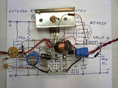
This is prototype assembled in a “spider” scheme to test the values, voltages and waveforms of components at different points in the circuit.
With that small heatsink you see in the photo, you can reduce the mosfet from 24V to 5V with more than 3A output with almost no heating. The coil I used in this assembly cannot withstand this current and gets very hot. Another thread with a larger section will be required. I added another electrolytic capacitor at the input to improve filtering, there was noise disturbing the switching, this may be due to dangerous assembly.
In welding tests:
From left to right: oscilloscope, A (top) output voltage 5V/section, B (bottom) mosfet gate voltage 5V/section, output ammeter 707mA, and output voltmeter 4.88V. Behind the variable power supply set to 13V and to the right is a huge 10 Ohm and many watt potentiometer that I use as a variable load. Installation of the weld between the marabuntas of the probes.
List of these ingredients:
1 Resistor 1/4 W 3K3 5%
1 Resistor 1/4 W 100 5%
1 Resistor 1/4 W 1K 5%
1 5.1V 400mW zener diode
1 Diode 1N4148
1 5.6nF ceramic disc capacitor
1 6.8nF ceramic disc capacitor
1 Schotky diode 1N5819 for 1A (I used 1N5822 for the 3A I have).
1 BC337 NPN Transistor
1 P-Channel IRF9530 Mosfet Transistor (I had it…)
1 470 microhenry choke
2 Electrolytic capacitor 100 microfarads 25V
A small piece of printed circuit
A radiator if more than 500mA is used
As a result, it absorbs 220 mA at 12 V (2.64 W) from the source when it delivers 478 mA at 4.95 V (2.366 W). I’ve tested up to 24V supply and up to 3A output at 5V and there is almost 200mV variation in output and mosfet heating is hardly noticeable. It doesn’t work well below 11V because with high currents the mosfet needs 10V at its gate to fully switch. While the regulation is not very good, it can serve as a previous step to reduce a very high voltage to the minimum acceptable for an LM78xx, thereby reducing overall dissipation and energy loss.
This is everything. It is possible to give it more stability or better performance by changing the components. I’ve chosen some that work over a very wide voltage range, although they don’t regulate very well. It’s not bad to be able to drop from 24V to 5V with 3A with almost no loss of energy in general heat…
5V 3A Switching Mosfet Regulator Circuit
Source: heli.xbot.es/regulador/regulador2.htm


Walking Led Light 555
Our circuit was considered little different from the usual circuit. Different from the usual operation of the CD4017 circuit.
Hopefully of interest to you. They remain in one direction lights are burning and burn progressing. Lighting sequence starts from LD1. Ie, starting from the beginning after burning LD16 LD1 goes out.
P1 potentiometer to set the speed for burning was made. Request in accordance with the potentiometer or poyansiyometr available. Led by the color of the LED current limiting resistors 330 ohms to 680 ohms should use.