You can use IR2104 MOSFET full bridge motor driver circuit in your high power motor projects. There are DIP and SMD version PCB drawings of the circuit. 7400 NAND gate IC is used in the signal input. The author faced many problems while implementing this project. An important detail is that if the supply voltage of the IR2104 circuit is taken from the motor voltage, if there is a voltage drop at high currents, the integrated may fail. So it is important that the power supply provides sufficient power.
Note: You can view and export PROTEL DXP PCB schematic files online from its official site https://www.altium.com/viewer/ (subscription required for export)
I am attaching the edited translation of the author’s description, there is useful information…
IR2104 Motor Driver Learning and Application Process
While using full-bridge chips like L293 or L298 to control DC motors is simple and inexpensive, due to their large internal resistance, the chips often overheat when controlling high current motors, resulting in overall low system efficiency. In an electric vehicle, excessive internal resistance of the engine control chip will cause the vehicle’s acceleration to drop.
During my summer vacation I dreamed of making a big wheeled or tracked robot and hoped it could run as fast as a bus, so I started researching how to use mosfets to control higher current motors.
First of all, I applied to the circuit diagram in the article “Driven by High Power DC Motor – ABU ROBOCON 2005 Competition Power Scheme”
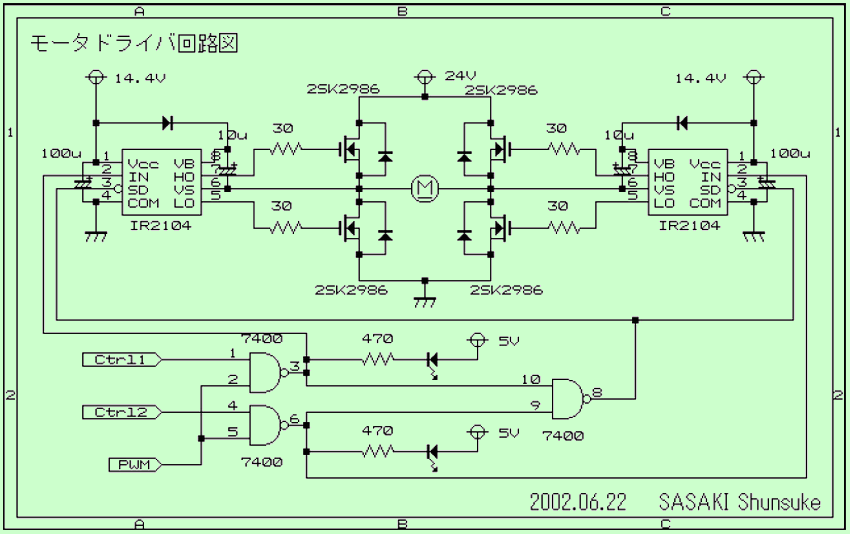
According to this schematic diagram, I made a full bridge driver circuit. I changed the resistor and capacitor values. I found that after powering up and an active continuous high level signal the circuit failed to start the engine and the ir2104 started to heat up and the irf540 was not driving. Then I replaced the ir2104, but the same event still occurs. With the oscilloscope measurement, I realized that the high (HI) side mosfet is not driven and the low side mosfet’s gap signal is abnormal, so the bridge is not opened. I changed the signal direction and the same problem persisted on the other half bridge
I’m starting to suspect something is wrong with the BOOTSTRAP capacitor, so I tried different capacitor values. However, the problem is still not resolved. Since I only have 6 ir2104s and they are all turned on and overheated, I bought a new batch of ir2104.
After replacing the ir2104 the circuit was working normally. I made a measurement with an oscilloscope to examine the driving voltage waveform on the gate leg of the high side (HI) mosfet. At the first stage where the source terminal was high, I saw the driving voltage of the high side (HI) mosfet suddenly go 10V higher than VCC. This is where strong acceleration comes into play. However, as time passes, the voltage gradually drops to the VCC voltage, and the conduction of the mosfet becomes less and less complete. Until the next pulse comes, the gate terminal voltage VCC returns to +10V, but gradually decreases.
That is, constantly driving the mosfet with a high level signal will cause the mosfet not to turn on completely, heating the mosfet and reducing the actual power of the motor. This problem can be solved by using the PWM signal, which allows the BOOTSTRAP capacitor to charge and discharge repeatedly, so that the high side (HI) driver voltage is kept at a relatively high level at all times.
If you want the engine to run at full speed, you can’t use high level all the time, but you have to use PWM with about 3% duty cycle. This is the biggest difference between the ir2104 ride and the 298 ride and other fullers.
It is suitable for different BOOTSTRAP capacitor values, different frequency PWM signals and different mosfets. The charge and discharge time of large capacitance value is relatively long, and the voltage drops relatively slowly, so it is suitable for PWM at a lower frequency; The charge and discharge time of a small capacitance value is relatively short, suitable for PWM a higher frequency. Although in the IR2104 datasheet it has given a calculation formula for the BOOTSTRAP capacitance, I prefer to find the appropriate capacitance value by experiments. Easier to do than laborious calculations, experiments allow me to understand how the system works.
Through experiments, I determined the capacitance value of 1UF. The capacitor uses low ESR capacitors to reduce leakage. Compared with high frequency PWM, the effect of leakage current in such a short time is negligible. In theory, however, leakage of the BOOTSTRAP capacitor will cause the open resistance of the high-base (HI) mosfet to increase.
After the circuit was installed, my robot car worked successfully. The performance of the car in full speed starting and sudden reverse is clearly better than using the L298 motor driver IC. The main reason is that the sudden directional current change is too large and the L298’s driving capability is limited, resulting in a small directional current change and small acceleration.
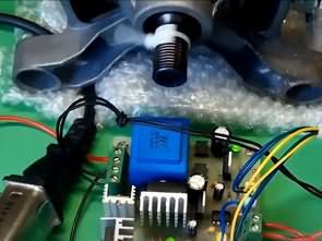
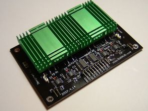
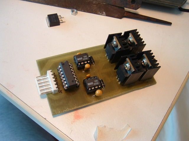
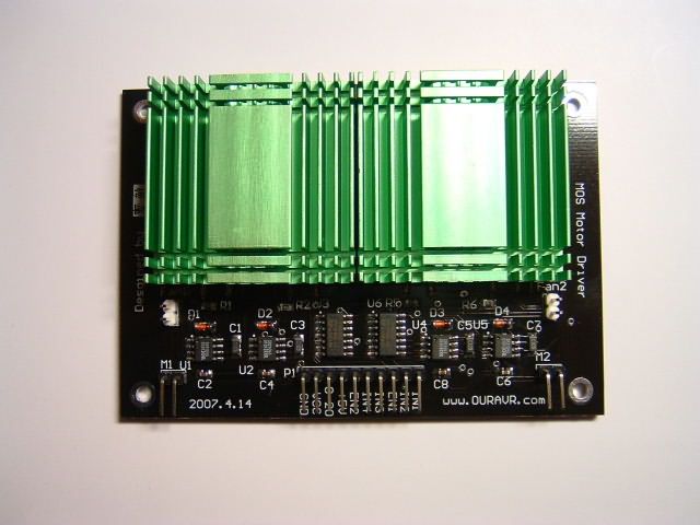
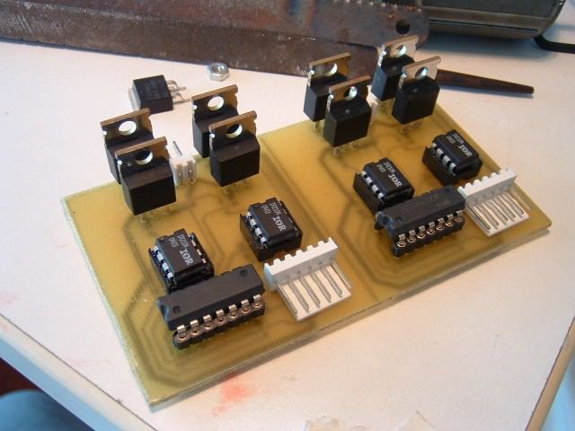
There were no problems with the circuit, so the circuit was basically terminated and I turned to the design of the printed circuit board. Since the mofet in the TO-220 package takes up a lot of vertical space and requires a cooler, I decided to use IRF540 in the SMD D2PAK package and other components were changed to the SMD package. I also added a heatsink and a fan above the mosfets to dissipate the heat. Cooling Lowering the temperature of the mofets greatly improves the working efficiency.
A week later I bought the PCB and also bought the SMD components and assembled it. I noticed that the mosfets were getting very hot, although the circuit was working normally. So I decided to replace the aftermarket TO220 with the original irf540 D2PAK package for comparative experimentation.
I soldered the original ir540s to the circuit without the heatsink installed. As I couldn’t wait to see the test results, I turned on the power without cleaning the pcb, and as a result, the IR22104 suddenly caught fire and split in two. I hastily turned off the power, but it was too late. After replacing the IR2104, the circuit still cannot work normally. As a result of the measurements, I realized that the problem was with the 74HC00. After replacing the 74HC00 and cleaning the board, the circuit worked fine. It occurred to me that the remaining pins of the 74HC00 are not connected to ground and the solder paste could be causing the leak. So, I attribute the main cause of this fault to the remaining pins of the 74HC00 not being grounded, causing solder paste leakage.
After the circuit is repaired, by driving the same engine, the original irf540 does not heat up, and the aftermarket or fake ir540 is seriously warm.
I saw you. I came to the capital of science and technology and looked for IRF540S everywhere but all the traders told me it’s not real, just fake. Other SMD mosfets I’ve found have low current. I used IRF540N instead of IRF540S.
After returning home I started trying to drive with a larger current, in the same circuit powered by a 2A regulated power supply I set the driving voltage and the ir2104 operating voltage to 12V and opened the current limit to maximum. The drive signal is 97% high level PWM and the motor is reversed every 1 second. When the motor returned, something unexpected happened: the motor stopped but the current was limited to 2A! At this point the components on the board should be starting to heat up! I quickly turned off the power. I touched the ir2104, it was hot! Fortunately it didn’t burn.
I turned the power back on to start the small engine and everything was normal. But as soon as the big engine reversed, the same thing happened again. After thinking it over and over, I attributed the problem to the current limitation of the power supply. Due to the large current when the motor is reversed, the voltage drops, so the operating voltage of the ir2104 drops below the normal range (10V-20V), and the ir2104 works erratically. Therefore, I want to point out that the supply voltage of the irr2104 should not drop.
After solving this problem, I thought that the design current of the circuit was very small.
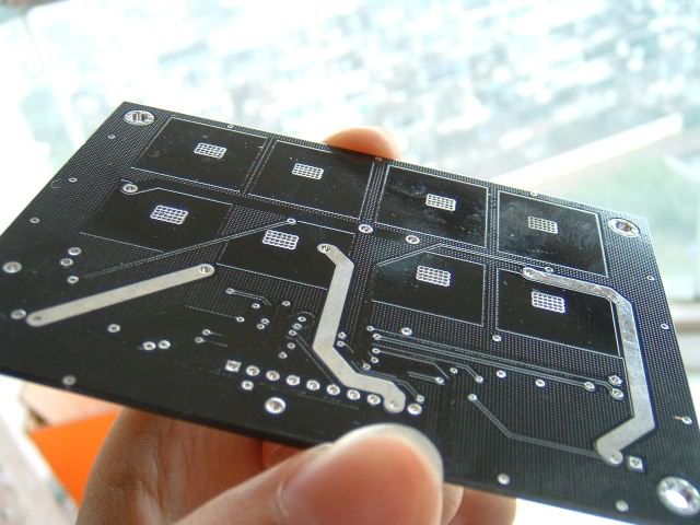
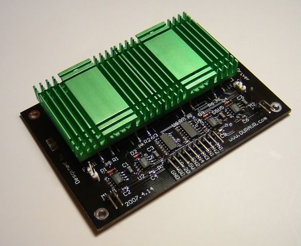
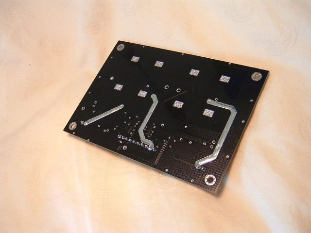
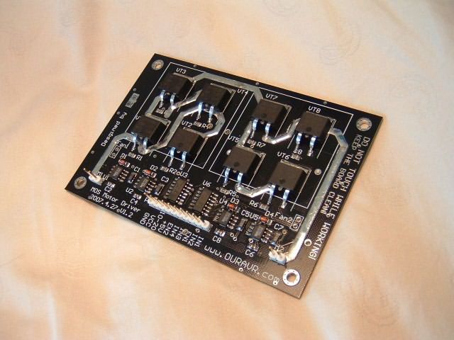
There were no component changes on the redesigned circuit board, I just focused on the wiring and heat dissipation. I used rectangular copper plating as a heat sink on the front and back of each mosfet and used multiple vias to connect the two pieces of copper plating where the mosfets are attached so the heat from the front can be quickly transferred to the rear for heat dissipation.
Additionally, in high current network I also used the SOLDER layer to remove the solder mask layer so it can be tinned to provide more current.
I received the PCB board yesterday and was looking forward to soldering it, cleaning the board and running the experiment and everything worked out. The heat dissipation performance of the circuit is excellent.
The IR2104 motor driver project is basically over, so I wrote this article to share my experience and happiness in the research process.
IR2104 motor sürücü PCB, şema dosyaları: ir2104-mosfet.rar pass: 320volt.com