Now let’s briefly circuit and try to explain the working principle. When we examine the data page UGN3503 Hall effect element elements are the analog watch that works. So the magnetic flux is genliğin to transfer to a suitable voltage. Do not try to apply these principles in clampmeter?
There used UGN3503 assumes the role of the coil. 1Amper must be set to 1 mV. Op1 knob was placed in the circuit for this purpose. Op2 is setting the reset knob. POT1 is brought to the center position for the item and the tool is connected in circuit DMM. 200mV DC level is selected. The measuring head is set to idle 00.0mv on a scale of DMM. If your multimeter automatic range 200mV must be selected manually.
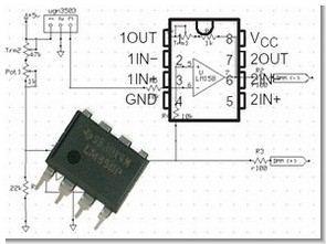
UGN3503 Hall Effect Sensor
Contents

High Current Measurement Calibration
a power tool spends another ampermetreyl current measured. The measurement unit is reset prior to measurement. Occuring spend the detected load current conductor is arranged between the measuring unit of a half-moon. Op1 is set by the current rating of 1 to 1 mV. DC load current to be measured is set dc200mv the DMM. Load the DMM AC, the AC should be 200mV. Circuit untested. However, in principle it should work. If the load 10 çkiy must be set as 10mV.
Hall Effect Sensor Current Meter Schematic


PIC16F84 Microcontroller Video Game Circuit (tetris, pong)
Made a beautiful project with PIC16F84, both in video and joystick control provided by a single processor OrCAD program prepared by pcb schematic and pic assembly .asm, hex code
It has been designed hardware of the system’s CIP game to play with different kinds of games. It has two outlets for standard joystick C64/Amiga/Atari, video and audio. The processor is a PIC16F84 operating in 12MHz and that generates the video signal (PAL and NTSC) and audio software. The description of the hardware is the same for both games, Pong and Tetris.