@Kapibara shared the battery desulfator circuit for battery resuscitation, recovery of the dead battery, I made a similar desulfator circuit for battery repair and tested for a long time. NE555 integrated desulfator circuit warranty circuit kits have been tested by many people, but I did not want to deal with the double coil, I applied the circuit made with the NE555 CD4049 duo. There are many videos on battery recovery, but there are either logic errors or incompleteness.
There are some very popular kits in the circuit I made. Description of the circuit;
The desulfurization Desulfator circuit (also known as Regeneration or electrolyte stratification) offers a way to bring dead batteries back to life and renew tired batteries. Desulfurization will not restore short-cell batteries or worn plates, but good results may be obtained depending on the condition of the battery.
When lead sulphate crystals build up on lead plates, removing them and thus renewing the battery is not an easy task. As more and more crystallization occurs, the voltage required to shift the crystals (dissolve them back into the electrolyte) also increases.
However, if you constantly apply high voltage to the battery, it will overheat and potentially explode. Pulsing is therefore used to ensure that only sulfate crystals are affected and that the battery does not overheat.
Desulfator Circuit Diagram
Contents
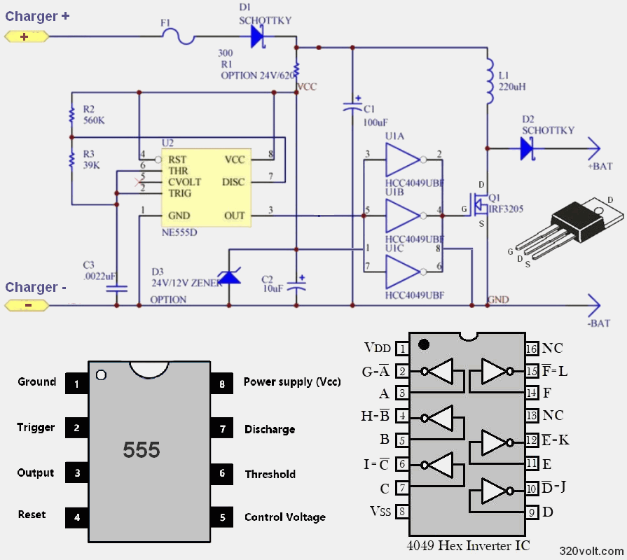
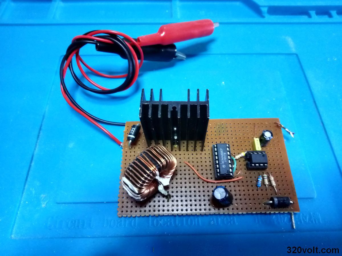
NE555 and CD4049 inputs are powered by 300-ohm resistors.
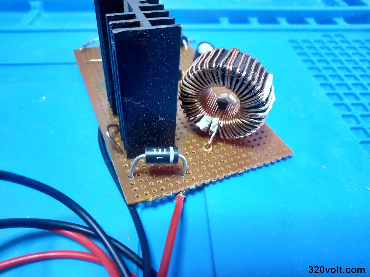
There is no need for a heatsink for the IRF3205 mosfet. I used a heatsink as a precaution, but it did not overheat. For the 100uf capacitor, the Low ESR rating has been deducted, I used a standard quality capacitor.
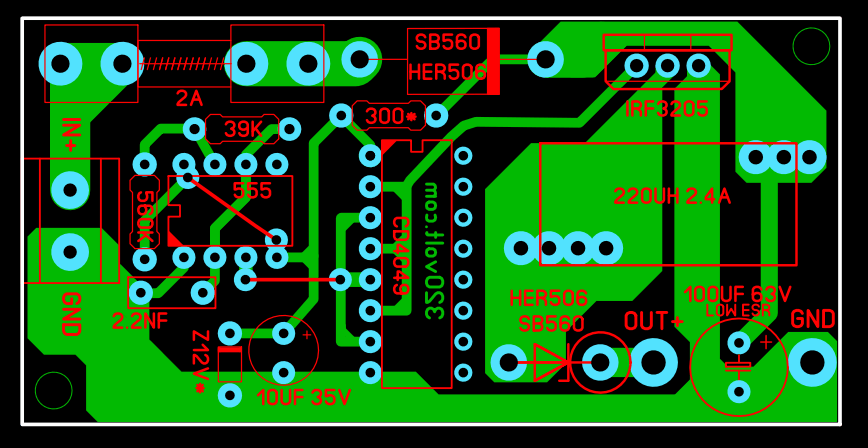
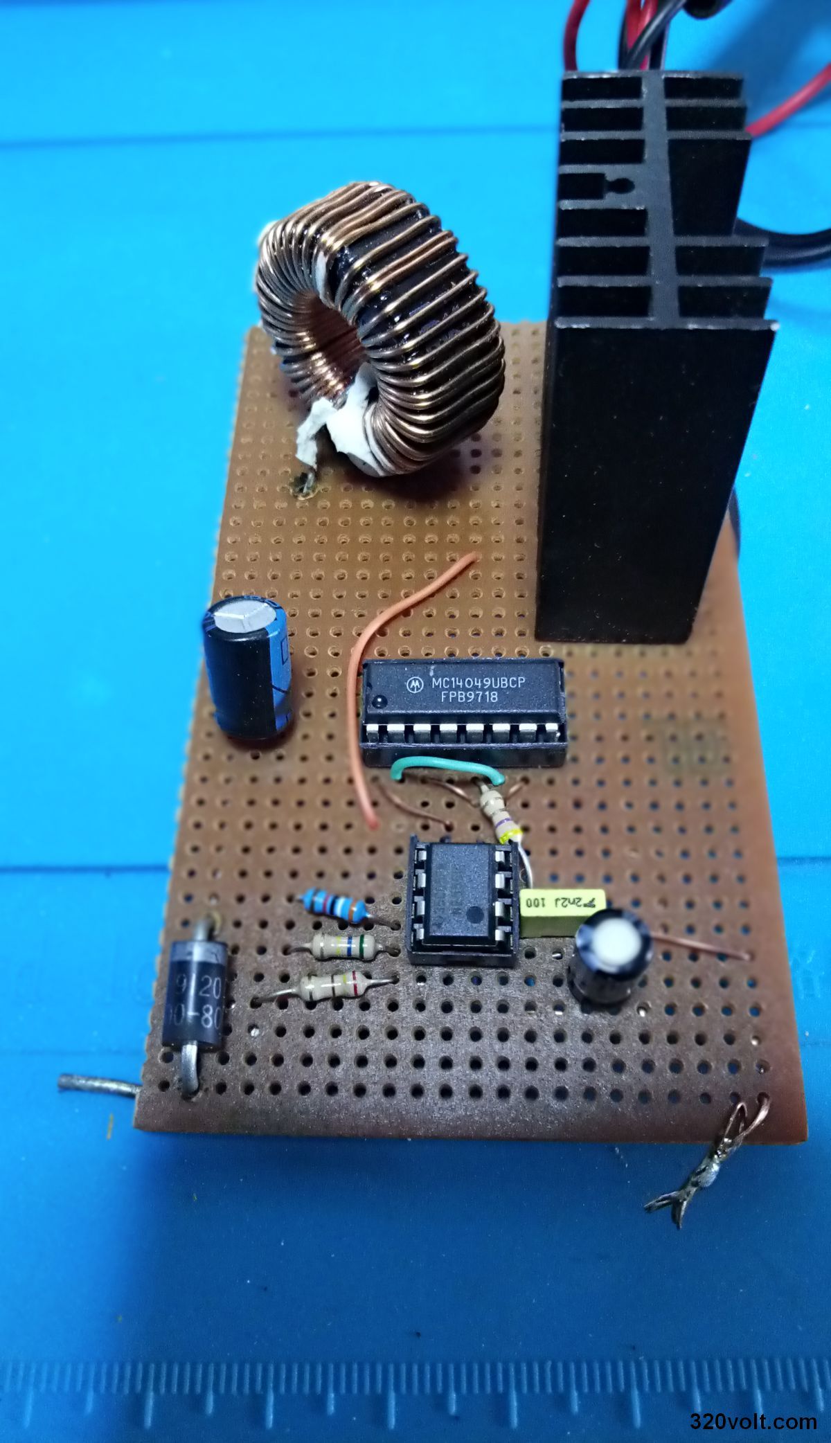
Desulfator PCB Drawing
I prepared the PCB drawing of the Desulfator Circuit with Sprint layout 6, it was checked according to the diagram, but I did not test it. I built the circuit on pertinax with holes, because I did not have a 5 amp fast diode, I used a 3A fast diode.
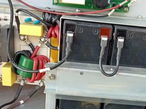
Preparation for battery repair
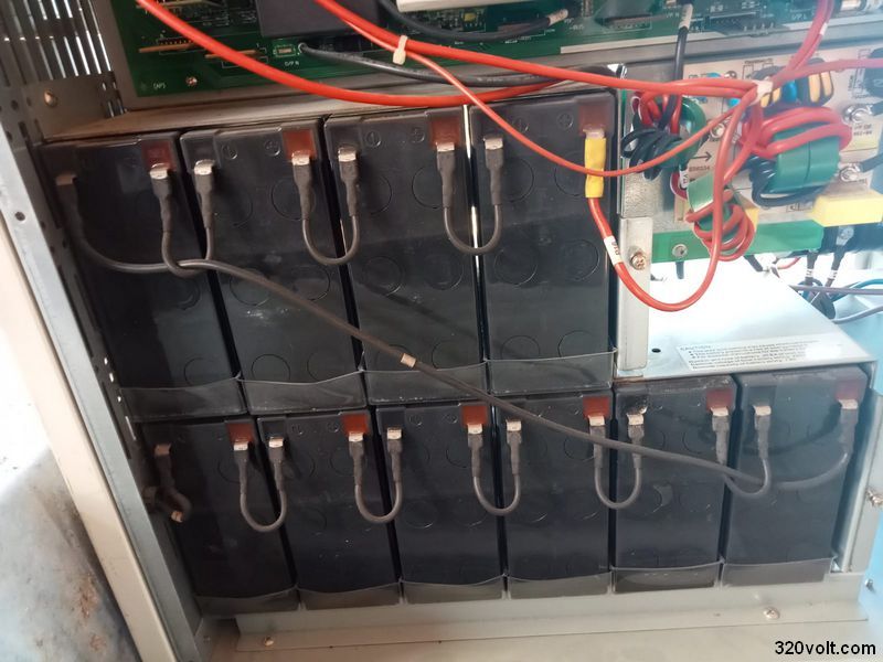
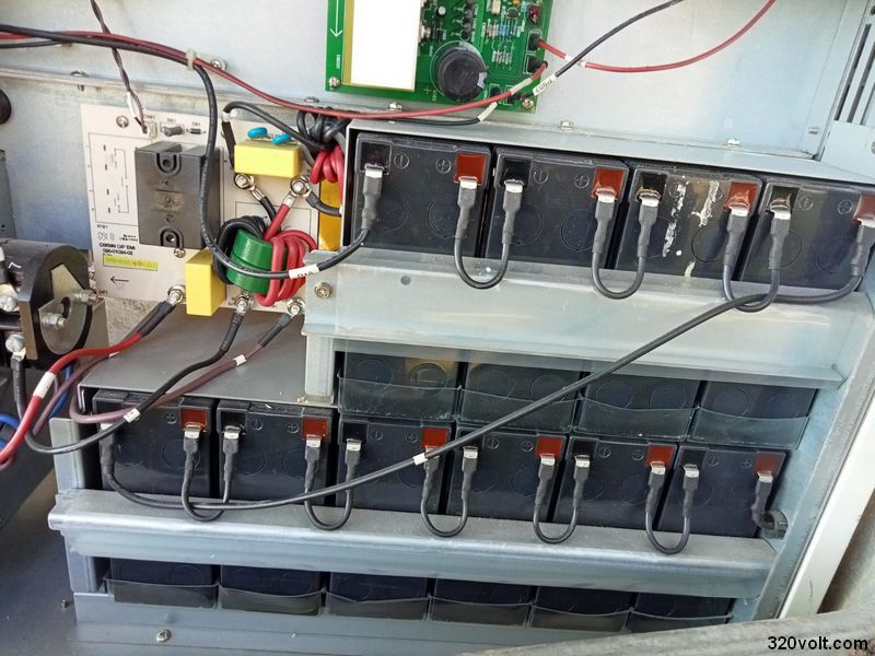
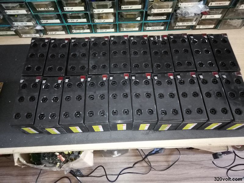
The reason I was dealing with the desulfator was to be able to test the 6kv UPS with 20 batteries after the repair. 20 batteries connected in series at 240vdc full charge, if I buy the cheapest battery, about 273v, it is a big expense for the job that is not clear..
The batteries of the device are CSB brand (quality.) The 12v 7ah device was taken aside and the machine was not used for 2…3 years when the working time from the battery was very low. The voltage of all batteries is around 1v…2v When I researched in detail, I saw that the water of the batteries needed to be renewed, although I knew this in UPS batteries. Generally, pure battery water is used, but I used acidic battery water because the batteries are dead and pure water that has been waiting for years will not save me. In a video, a 12v 7ah battery was repaired with acidic water taken from a car battery.
I bought acidic battery water from the industry and added 6ml of acidic battery water to all the cells of the batteries (6 in each battery), shook the batteries a little, and left them outside overnight without plugging in.
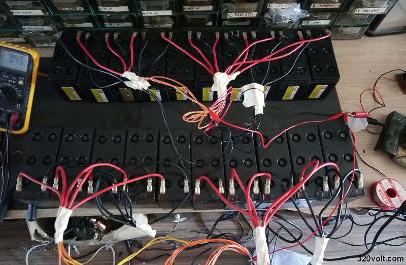
I have searched a lot about the 6ml ratio, there is nothing clear, some fill water until it overflows, some until it passes the plate a little, these seemed too much to me. When I measured the next day after topping up the acidic battery water, all the batteries were around 6v…7v. I connected all the batteries in parallel and connected the desulfator circuit. In fact, it is healthier to do it with one-by-one connection, but there are 20 batteries, it will take a long time.
Note: It takes days, weeks for the desulfator to clean the battery plates, depending on the condition of the battery, my batteries recovered in almost 3 weeks, but I operated 12 hours a day, I left it on at night and did not take any risks. Every day the batteries recover. For example, in the first days, when I disconnected the desulfator from the power supply and disconnected it from the batteries, I measured 8…9v, but the next day it dropped to around 6…7v, days later there was less voltage drop.
Attention: battery acid is harmful, you should use gloves and mask
12v adapter is given for kits sold in the market, but I have adjusted the operating voltage of the circuit around 13.8v in the regulated power supply, taking into account the diode and transistor losses. The designer of the circuit has already run the circuit with a direct charger. The circuit gives voltage between 20v….30v without battery connection.
In the first study, the battery desulfator circuit drew 150mA current, as the days passed, the current increased, about 2 weeks later, it came to around 1.8a, then the current started to decrease with each passing day, the last time it was around 600ma, most likely it would have dropped to around 150mA after a few days, the desulphation process would have been completed, but I got bored. It’s been a few weeks 🙂
I placed the batteries in the UPS device and made the connections. The device worked. I connected a 300w bulb to the output. After 1 hour, the UPS buzzer started to beep more frequently. I turned off the device without waiting for it to turn off, I guessed it would take another 1 hour + 10…15 minutes.. the purpose is not to use the device with these batteries, but just to test it..
Now I have done the first discharge, it needs to be recharged. At this stage, another problem arose (information pollution is full, or that’s how it is) in many narrations, they fill the water and close the lids and go to the charging process. gas is released.
For this reason, the first charge should be charged in an open area or in a well-ventilated place without attaching the plugs and caps.
In addition, generally, the desulfator process is done first and then the desulfator process is done, I did the desulfator process, meanwhile, the batteries are slowly charging. Since the circuit I used works with an external adapter, it was not a problem. Many people use a circuit powered by battery voltage, device.
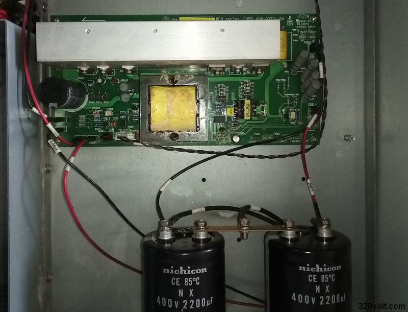
6Kv UPS 273V Charger Circuit
In a problem, the UPS appeared in the charging circuit. Fortunately, it was not a major malfunction. I found the schematic of the charging floor (I would have struggled if the schematic were not there). It is used in UPS devices between 6Kv..10Kv. The circuit is based on the UC3845 2SK727 mosfets with the EEL16 transformer. It reduces the input voltage of around 600v DC to 273V charging voltage, and the MCR265-10 thyristor is used at the output.
Finally, even if the batteries are repaired and go for 1…2 hours in the load tests, I will not use them in a 6Kv UPS device. In such high-power devices, battery renewal is a must. Repaired old batteries can be used as low-power UPS, searchlight, etc. Can be used with. But the age of the battery is important as well as its quality.
When the UPS worked without any problems, I used the remaining batteries in an old 4-battery UPS device for lighting and TV. It worked for 20 minutes with a 300w bulb. With 8w led lamp and 82 screen LCD TV, it will go longer, maybe a few discharges, after charging, it may take longer..
PCB of the desulfator circuit, schematic drawings and 6Kv UPS charging stage diagram 28053a.rar pass: 320volt.com


