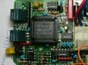
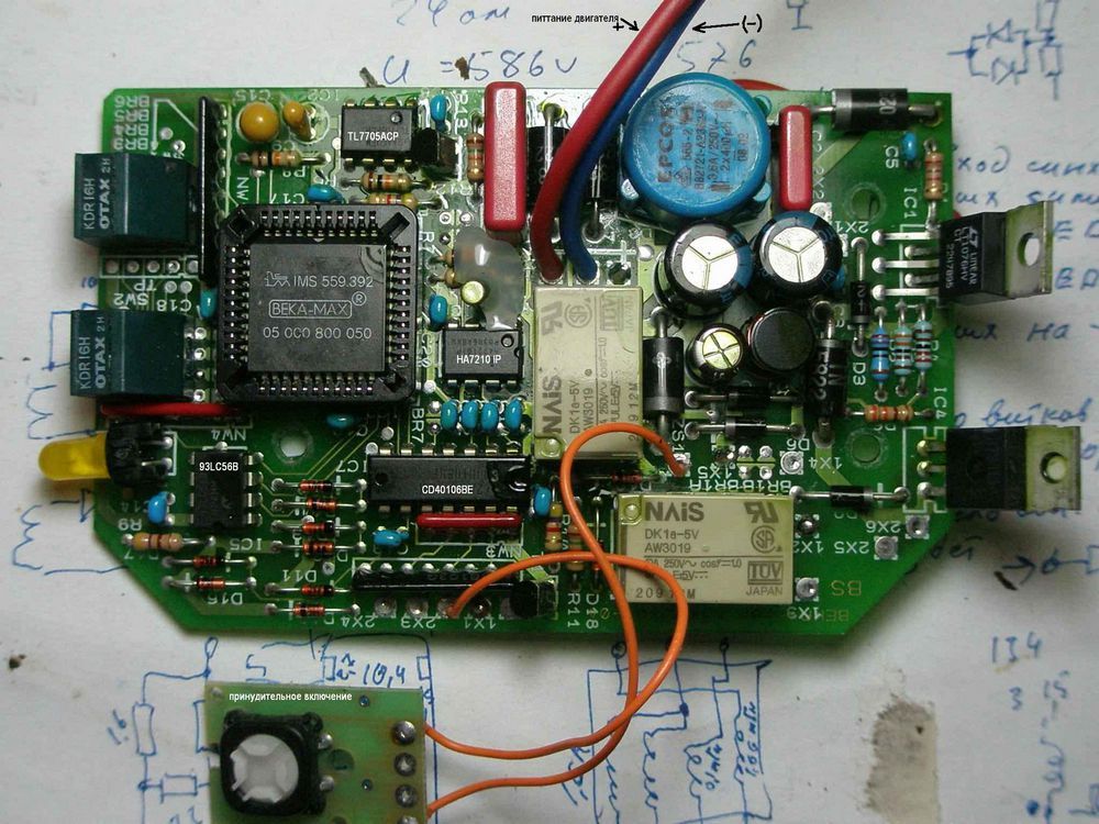
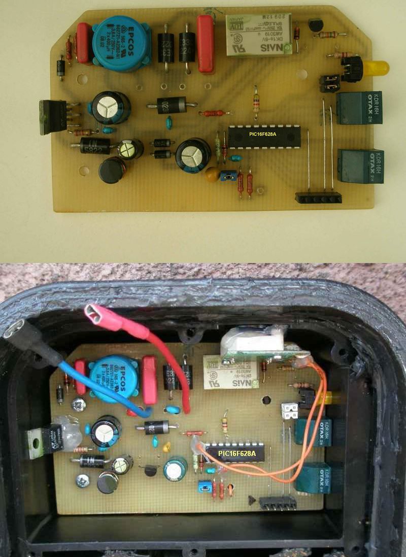
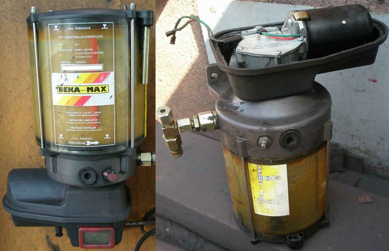
BEKA-MAX Type S-EP 4 pump is used for central lubrication of various mechanisms and equipment units. BEKA-MAX Since there is no IMS 559. 392 integrated in the original pump card, the author has made a clone pump control circuit using a PIC16F628 microcontroller. There is a pcb drawing prepared with the source Mplab asm and hex codes of the BEKA-MAX Type S-EP 4 Pump Control project with sprint layout. Description taken from source site Posted by Андрей Сахненко
Let us consider the motor control circuit. I wanted to simplify it by using the BTS113A transistor as a switch. But there were inconsistencies with the power filter installed on the L1. I had to drop it as simplification is not possible without loss of quality.
But the switching regulator LN1076 behaved somewhat incomprehensible. When the LED was operating in pulsed mode (blinking at a frequency of 1 second), the output voltage would float in the form of a saw with a ripple amplitude of about one volt. LED current consumption is only 3mA. However, if the stabilizer was loaded with 250mA, there was a slight drop in output voltage of about 0.01V.
Using the LM7805L, the problem was solved, the +5V output voltage stabilized. Even turning on the relay (40mA) did not create any disadvantages. And the diodes D6 and D7 were removed, separating the power supply circuits of the relay and control.
The large capacity installed after the LM7805L keeps the PIC16F628 microcontroller running for about one second. This is enough to save all the timer registers to the nonvolatile memory of the PIC16F628 microcontroller. As a result, a stabilizer was installed instead of two diodes.
Also, motor protection (24V 12W) has been regulated for overload. In the tests performed (oil line clogged), the pump consumed 0.4A of current without overload, while 400 kg/cm^2 explosive pushed the valve. And there were no cases of engine failure.
I also did not change the system to enter the timer settings and run indicator. I left everything as it was in the factory version. The only thing that leaves the LED on in pause mode because another time you don’t know if the pump is on.
All parameters of the time settings have been preserved as in the original version.
Lubrication 1 – 16 min. Step 1 min.
Pause for 0.5 – 8 hours. 0.5 hour step
Functions performed when the power is turned off: Saving the current time and operating mode in the memory of the PIC16F628 microcontroller.
When power is applied: Restore time and operating mode. Indication of lubrication mode via an LED. It fires at 1 second intervals. Pause mode indicator, LED steady on.
When the power supply drops below 15V: Saving the current time and operating mode in the memory of the PIC16F628 microcontroller. Low power indication, – LED’s intermittent light (interval 0.2s).
A few words about the program.
If the watchdog timer is not applied, if the pump starts to fail, this will be immediately evident by the amount of excess oil being squeezed out of the lubricated units. That is, during operation, WDT will continuously reset the microcontroller to the start of the program, and this will also be reflected in the amount of lubricant.
He applied a power reset MCLR, hoping that all transients on the power supply had already been completed. I would also like to point out that the subroutine with the function of clearing the running registers immediately after the microcontroller is initialized is very useful, as it gives time to temporary operations on the microcontroller modules after power-up.
The button is queried in the main program loop and is approximately 20 ms. The overflow only interrupts TMR1. The formation of the time standard at 0.5 s is based on this. The stability of the internal oscillator is sufficient. No additional crystals can be used. Precise selection of TMR1 preset values was made with the stopwatch.
A one-minute pause was introduced to restart the microcontroller after a voltage drop above 24V. It is made in such a way that there are no unnecessary entries in the EEPROM memory. According to the scenario, when the 24V voltage drops to 15V, it is considered as the power cut from the pump. The microcontroller records the timer registers. Save space, timer is triggered for ~1 min.
During this time, the capacitor feeding the microcontroller should be completely discharged. If there is only one failure in the recording, then after 1 minute. the program will go to the “start” vector.
Schematic, pcb and code files of BEKA-MAX Type S-EP 4 Pump Control Circuit 28100a.rar pass: 320volt.com
Source: chipmk.ru/razdely/13-promyshlennaya-pribory/94-remont-pompy-beka-max


