ESR meter is a device used to measure the equivalent series resistance (ESR) of capacitors. Built on the PIC16F690 microcontroller, the previous version uses PIC16F873A) The ESR meter circuit is very small in size and its features are very good. In the ESR Meter Milliohmmeter project, the PIC16F690 program was written in MikroC. Proteus drawing, model as well as source code is available.
ESR Meter Features:
- Supply voltage, 1.1v – 1.6v
- Average current consumption: in measurement mode, 50mA in standby mode, 16mA in sleep mode, 55μA
- ESR / R measurement error in the range 0.01 – 60 Ohm, max, ±% (3 + 2 display units)
- Total measuring range ESR / 0.01 – 700 R, Ohm
- Capacitance measurement error 0.1 – 9999 μF, ±% (5 + 2 unit indication)
- Total capacitance measuring range, 0.1 – 999999μF
- Measuring range in “Milliohmmeter” mode, 0.01 – 9.00 Ohm
- The maximum voltage of the charged measured capacitor, 500v
- Maximum capacitor energy absorbed by the shield, 10J
- Transition time from standby to sleep mode, 60s
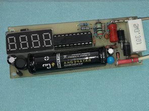
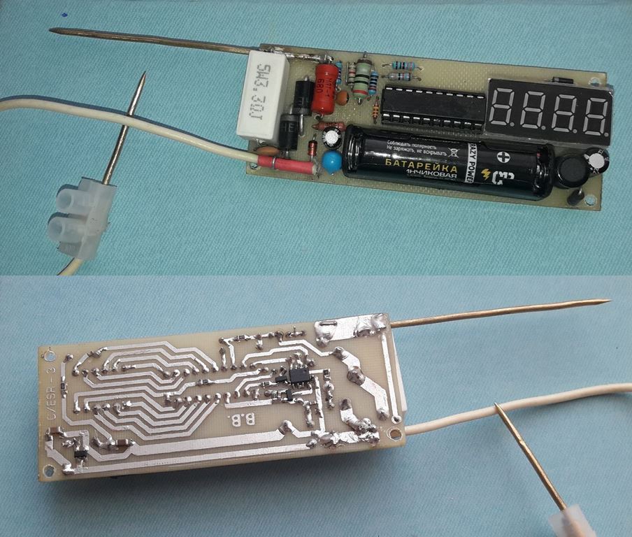
- Working images of the first version of the circuit (V1) latest version V3
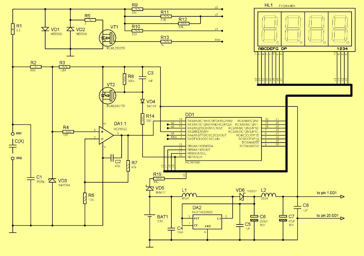
Milliohmmeter ESR Meter Circuit Diagram
Description of ESR Meter Operation
STANDBY MODE. When the probes are not connected, the device goes into standby mode and the middle parts of the 2nd and 3rd digits light up alternately on the display. In this mode, for 8 seconds and then every 16 seconds, for 2 seconds, the battery voltage is displayed as “bAtt” + “uX.XX” (hereafter “XXXX” + “YYYY” form register means alternative). “XXXX” and “YYYY” indicator at 0.5 s intervals), where Х.ХХ – battery voltage. If nothing is connected to the device for 60 seconds, the indicator will turn off completely and go into sleep mode. The instrument may remain in sleep mode for a long time until the probes are short-circuited with each other or the measured element is connected to them.
STANDBY MODE + CHARGED BATTERY. If the battery voltage is less than 1.1V, then 8 seconds after entering the standby mode, the first indicator of the battery voltage changes slightly – “bat.L” + “uX.XX” and immediately after that the device “falls asleep” , that is, after 10 and 60 not seconds. When the battery voltage drops below 1.0V, the device will turn off and on only after replacing the battery.
CAPACITOR MEASUREMENT. When the measured capacitor is connected to the probes, data such as “cXX.X” + “rX.XX” (capacitance and resistance) will be displayed on the screen. The first part can take the following other values: “cXXX” – capacitance 1 – 999 µF; “XXXX” – capacity 1000 – 9999 uF; “F.XXX” – capacity 0.01 – 0.999 F; “F.99ˉ” – capacitance 0.999 F. The second part can take the following other values: “rXX.X” – second current limit used during measurement – 1mA; “RXXX” – third current limit applied during measurement – 0.1mA. All numerical values of the second section mean resistance in Ohm-ah. If the capacitance is too low or the resistance is too high, “c __” + “r99ˉ” is displayed.
RESISTANCE MEASUREMENT. When a resistor is connected to the probes, “RES _” + “rX.XX” type data will be displayed on the screen. Other meanings of the second part are the same as in the previous case.
MILLOMMETERS IN CIRCUIT. If you keep the probes short-circuited (or with a resistor connected) continuously for 30 seconds, the device will start to display a message like “dir_” + “_rES”, which means switching to the mode of measuring low resistances at a constant measuring current. . Switching to this mode occurs when the probes are turned on no later than 4 seconds after the message appears. The values do not change every second, the measured resistance is constantly displayed. In this mode, the stability and accuracy of the measurement is higher.
A measuring current of 10 mA is constantly supplied to the probes (if they are open, the current flows through the diodes VD1, VD2). At the same time, the result is practically not affected by the capacitances connected in parallel with the measured circuit, as well as their inductance when measuring the active resistance of coils and transformers. Measuring range 0.00 – 9.00 Ohm, if exceeded the device displays “r.99ˉ”. In this mode, the operation of the device is similar to the operation of a milliohmmeter, only the measurement resolution is not 1 mOhm, but only 10 mOhm, but the measurement limit is larger – 3.6 Ohm against 9 Ohm. Exit mode occurs when the device is found with open probes for two minutes.
CALIBRATION. This mode is activated if the probes are not turned on for more than 4 seconds when the message “dir_” + “_rES” appears from the previous point. Two seconds of text changes to “CALI” + “CALI” (meaning permanent text), then “OPEn” + “Probe” (Open probes) appears when you turn on the probes. After that, if you do not disconnect the probes for 10 s, an alarm output will occur (“CALI” + “Err_” 2s) and the device will go to sleep with an open output, as it is mistakenly interpreted as a short circuit. If you turn on the probes in time, after 3 seconds the device will offer to turn them off again: “CLOS” + “Probe”. Again, no later than 10s, it is necessary to reliably turn off the probes of the device. After that the calibration is completed correctly and “CALI” + End_” is displayed.
When the probes are turned on during the calibration process, the initial current limit (10 mA) is calibrated and the internal resistance of the wires and probes during the short circuit is calculated, then subtracted from the measured ESR/R. value. In the latter case, if you do not turn off the probes for more than 10 seconds, the resistance of the probes will remain at zero. The result of the calibration is written to the EEPROM and is retained even if the battery is disconnected.
MEASUREMENT OF SUPER CAPACITORS. This Feature occurs when a charged super capacitor is connected to the device. Suppose a 0.47 F supercapacitor is connected to the device and charged to 4 V (remember 10J max energy!). It will take approximately 10 seconds to discharge by the instrument to the 50 mV required to start the measurement! At this time, the device informs the user about the supercapacitor discharge process: “ion _” + “Uˉ-_”. There is one caveat, however: the device will only be able to detect a connected charged supercapacitor if its positive terminal is connected to the top pin of input connector S1 and the negative pin is connected to the bottom one. Otherwise, the device will detect it as a zero resistance resistor. In this case, after about 15-20 seconds, the super capacitor will discharge and the device will measure its parameters. Although the device remains operational in all cases, this is the only case where the polarity of the probes connection is important to the device.
ESR Meter all files download: 28063a.rar pass: 320volt.com
Source: cxem.net/izmer/izmer208.php


