
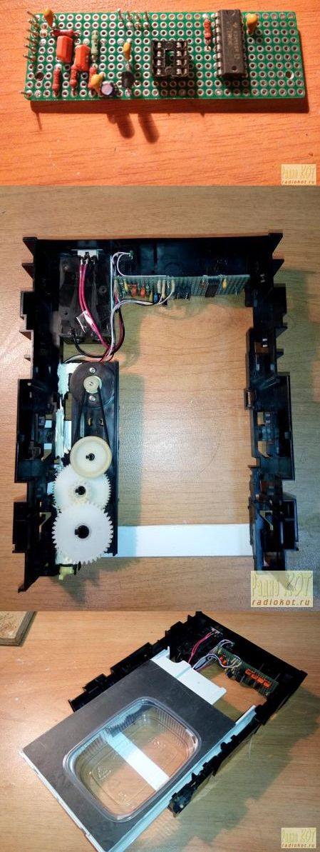
For the author, the automatic feeding machine for the wedge is the easiest mechanical part for the application. they insert a plastic container all of which is placed on the CD present on the CD-ROM and put the ready-made cat here. Attiny13 Automatic feeding circuit A simple driver circuit is used for engine control based on the Attiny13 microcontroller. The operating voltage of the feeding circuit is 9v Attiny13 supply 78L05 regulator provided with the project’s proteus simulation scheme, source codevision avr c, hex code files are available.
When the over voltage is applied, the D2 LED flashes. By pressing the button briefly, the sled opening time can be selected as 12, 24, 36, 48 hours. The time setting is indicated by led: 12 hours, 2 times 24, 3 times – 36, led light without pause. Pressing the button for a long time, if necessary, opens or closes the rails. This does not affect the Timing setting.
Timer ready modules are sold more easily to control the application. This circuit can be done by using CD-ROM mechanism with different circuit, devices and automatic feeding system.
Automatic Feeding Circuit Schematic

source: radiokot.ru/circuit/digital/automat/118/
FILE DOWNLOAD LINK LIST (in TXT format): LINKS-25943.zip


Automatische Fütterungsmaschine mit CD-ROM-Mechaniker
Für den Autor ist die automatische Zuführmaschine für den Keil der einfachste mechanische Teil für die Anwendung. Sie legen einen Plastikbehälter ein, der auf der CD auf der CD-ROM liegt und legen die fertige Katze hier ab.
Attiny13 Automatische Einspeisung Eine einfache Treiberschaltung wird für die Motorsteuerung auf Basis des Attiny13-Mikrocontrollers verwendet. Die Betriebsspannung des Speisungskreises ist 9V Attiny13 Versorgung 78L05 Regler mit dem Proteus-Simulationsschema des Projekts zur Verfügung gestellt, Source Codevision avr c, Hex-Code-Dateien sind verfügbar.
Wenn die Überspannung anliegt, blinkt die D2-LED. Durch kurzes Drücken der Taste kann die Schlittenöffnungszeit auf 12, 24, 36, 48 Stunden eingestellt werden. Die Zeiteinstellung wird durch LED angezeigt: 12 Stunden, 2 mal 24, 3 mal – 36, LED-Licht ohne Pause. Durch langes Drücken der Taste werden die Schienen geöffnet oder geschlossen. Dies wirkt sich nicht auf die Timing-Einstellung aus.
Timer-fähige Module werden einfacher verkauft, um die Anwendung zu steuern. Diese Schaltung kann unter Verwendung eines CD-ROM-Mechanismus mit verschiedenen Schaltungen, Vorrichtungen und einem automatischen Fütterungssystem durchgeführt werden.
600W DC DC Buck Converter Circuit 60V Input to 12V 50A
600W DC DC Buck Converter Circuit 60V Input to 12V 50A
The input voltage of the 600W DC DC Buck Converter circuit is 35V … 60V DC. output 12V 50A LM5116 for control of the DC DC Buck Converter is capable of use Adjustable operating frequency from 50kHz to 1 MHz available Current limit, soft start etc. it has a lot of features. The output power of the 12V 600W 50A DCDC Converter circuit is very high, this power can be provided by combining two units of the same LM5116 synchronous operation. LMC555C LMC7101 integrated circuit. With full load ( 25a-50a ) and short-circuit, heat test with 35v, 48v, 60v input voltage.
PCB design of the DC DC Converter circuit PCB size is very small compared to SMD type materials, it is possible to make thicker slim of the nubes and to make the wrapping with copper strips. Efficiency of the BSC123N08NS3 and BSC047N08NS3 The cooling of the MOSFETs is probably done on the PCB and the fan or the cooler is being installed. There are detailed drawing (ing.) PCB drawing and gerber files ..
12V 50A DC DC Buck Converter Circuit Schematic
Machine d’alimentation automatique avec mécanicien de CD-ROM
Pour l’auteur, la machine d’alimentation automatique pour le coin est la pièce mécanique la plus simple pour l’application. ils insèrent un récipient en plastique qui est placé sur le CD présent sur le CD-ROM et y met le chat prêt à l’emploi. Circuit d’alimentation automatique Attiny13 Un circuit pilote simple est utilisé pour le contrôle du moteur basé sur le microcontrôleur Attiny13. La tension de fonctionnement du circuit d’alimentation est de 9V Attiny13, un régulateur 78L05 fourni avec le schéma de simulation du projet, source codevision avr c, des fichiers de code hexadécimal sont disponibles.
Lorsque la surtension est appliquée, la LED D2 clignote. En appuyant brièvement sur le bouton, le temps d’ouverture du traîneau peut être sélectionné comme 12, 24, 36, 48 heures. Le réglage de l’heure est indiqué par la led: 12 heures, 2 fois 24, 3 fois – 36, lumière led sans pause. Si vous appuyez longuement sur le bouton, si nécessaire, vous ouvrez ou fermez les rails. Cela n’affecte pas le paramètre Timing.
Les modules prêts à l’emploi sont vendus plus facilement pour contrôler l’application. Ce circuit peut être effectué en utilisant un mécanisme de CD-ROM avec différents circuits, appareils et système d’alimentation automatique.