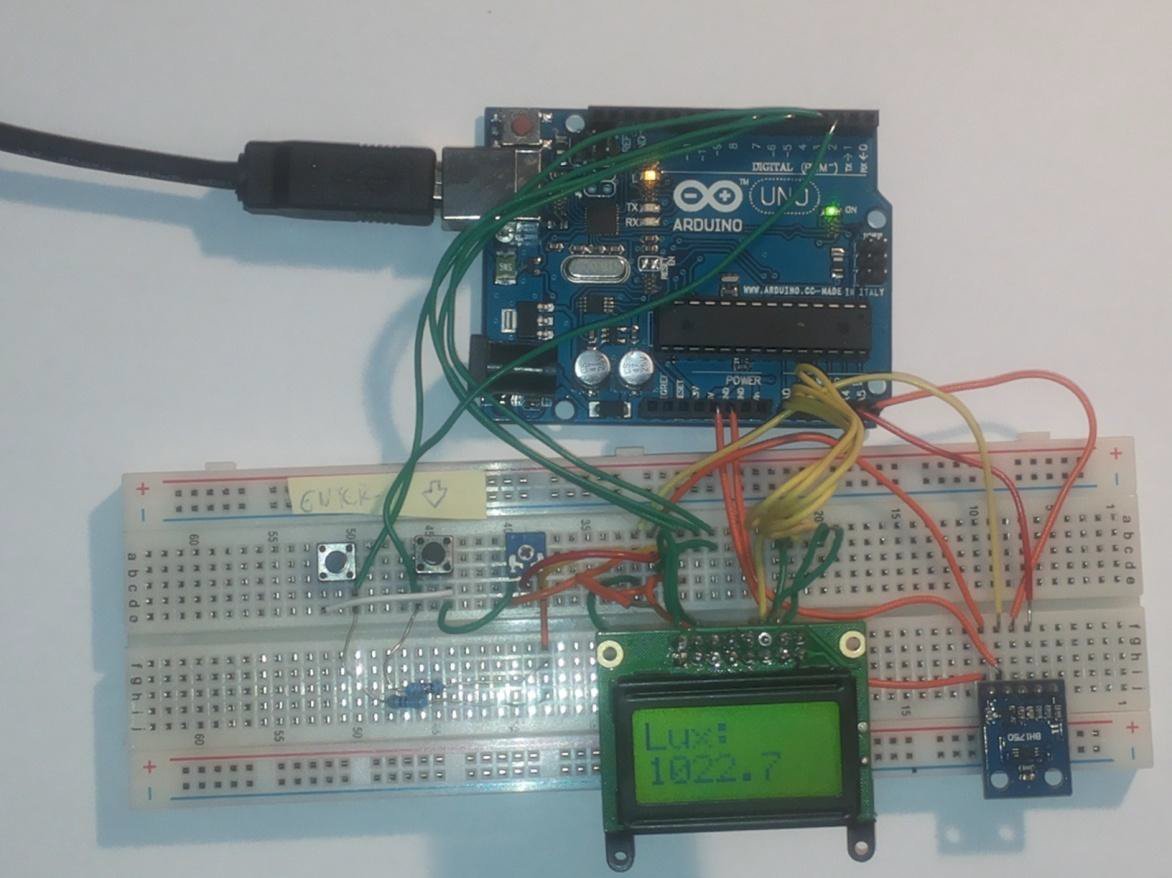
When reviving a luxmeter on a printed circuit board, there was a problem that the proposed connection is inoperative.
The first option was quickly verified by measuring the printed circuit board with a multimeter. An error was found in the wiring. Grounding of MCP1258 was not connected to dissolved ground. The defect was fixed, but the device was still inoperative.
The Arduino UNO programmer, in which the ATmega328 single chip is fitted, can provide not only 5V voltage, but also 3.3V power. When testing the power supply voltage change, I found that although all components are compatible with 3.3V, but the wiring is not able to work with such a small voltage. The problem could be that the selected components would need more current than 2 AA batteries to provide. By interrupting the PCB, it was experienced to power the circuit with 5V from the programmer. The interruption had to be made so that the voltage difference did not damage the components in the wiring.
With this in mind, it was found that the error had to be made in PCB design. Looking at the connection, I found that the flying capacitors of the MCP1258 I had designed badly. This error was corrected, but the luxmeter printed circuit board device remained inoperative. When checking components, it was found that the choice of MCP1258 stabilizer was unsuitable because this type cannot add enough current to the circuit. For a time reason, the new wiring design could not be implemented, so the luxmeter was left on the test panel because it was fully functional.
Luxmeter Graphics interface software
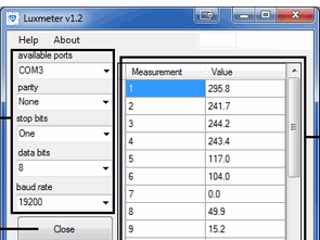
In the following, a graphical interface software has been designed so that the stored light intensity values can be transferred via the USB peripheral to the computer. A good solution is virtual serial communication (COM). In order for the virtual serial port to work properly, the AVR and PC parameters must be set appropriately.
Selected settings:
Baud rate: 19200 bit / s
parity: none
data bits: 8,
stop bits: 1,
handshake: none.
When running the application, you need to select the communication interface (COM) that controls the reader. Communication settings are pre-defined, no need to be set. If the communication interface (COM) is not accessible because it is being used by another program, it will throw an error message. Until the serial port is busy, the program cannot be used.
![]()
FILE DOWNLOAD LINK LIST (in TXT format): LINKS-26125.zip


Arduino YUN Security Project USB modem PIR, IP Cam FTP
Arduino YUN Security Project USB modem PIR, IP Cam FTP
Deals with the design of a special security system in which, apart from the usual parts such as camera and motion sensor, a USB dongle will be used to send the recorded videos via UMTS or LTE mobile networks to the server where they can be viewed. Nowadays, when mobile operators offer unlimited tariffs and high-speed internet, this solution is very advantageous because we are not limited by the length of the Ethernet cable that we have to connect to the camera or the range of the Wi-Fi router when installing the camera. The only condition is that the area is covered by a high-speed Internet operator.
The aim of this thesis is to study the possibilities of transmission of video signals in nationwide mobile networks GSM, UMTS and LTE, as well as formats of output video signals from cameras and types of sensors for motion indication. Based on this knowledge, a block diagram of a system for monitoring the disruption of space with a focus on video transmission is proposed.
Projet Luxmeter Arduino UNO (LCD USB)
Lors de la réactivation d’un luxmètre sur une carte de circuit imprimé, il y avait un problème que la connexion proposée est inopérante.
La première option a été rapidement vérifiée en mesurant la carte de circuit imprimé avec un multimètre. Une erreur a été trouvée dans le câblage. La mise à la terre du MCP1258 n’était pas connectée à la terre dissoute. Le défaut a été corrigé, mais l’appareil était toujours inopérant.
Le programmeur Arduino UNO, dans lequel la puce unique ATmega328 est installée, peut fournir non seulement une tension de 5 V, mais également une alimentation de 3,3 V. Lors du test du changement de tension d’alimentation, j’ai constaté que, bien que tous les composants soient compatibles avec 3,3 V, mais le câblage ne peut pas fonctionner avec une si petite tension. Le problème pourrait être que les composants sélectionnés auraient besoin de plus de courant que 2 piles AA pour fournir. En interrompant le PCB, il a été expérimenté d’alimenter le circuit avec 5V du programmateur. L’interruption a dû être faite pour que la différence de tension n’endommage pas les composants du câblage.
Dans cette optique, il a été constaté que l’erreur devait être commise dans la conception des PCB. En regardant la connexion, j’ai trouvé que les condensateurs volants du MCP1258 que j’avais mal conçus. Cette erreur a été corrigée, mais le dispositif de carte de circuit imprimé du luxmètre est resté inopérant. Lors de la vérification des composants, il a été constaté que le choix du stabilisateur MCP1258 n’était pas approprié car ce type ne peut pas ajouter suffisamment de courant au circuit. Pour une raison de temps, la nouvelle conception du câblage n’a pas pu être mise en œuvre, de sorte que le luxmètre a été laissé sur le panneau de test car il était entièrement fonctionnel.