The amplifier gained popularity with its ease of assembly, excellent repeatability and acceptable characteristics, while having a simple circuit, and of course the advantages of class-B (relatively high efficiency and good thermal stability), without the inherent distortions of this class. using the NE5532 operational amplifier, there is no need to introduce a zero offset adjustment unit, as is done in the original circuit (variable resistor R5). At the output of the NE5532, the DC component is practically zero. Removed positive feedback in the Modern version. The component values have also been adjusted.
RMS 100W Amplifier Technical Characteristics
- Supply voltage: ± 35V.
- Output power: 4 Ohm 100W.
- THD: 1kHz, 4 Ohm 0.005% 20kHz, 4 Ohm .0.022%.
- Amplified frequency range (relative to -1dB) 30Hz – 70kHz.
- Short circuit protection up to 8A.
- Input sensitivity 0.7V
There is also a delay in connecting the speaker system and protecting it from a constant voltage at the output.
RMS 100W Amplifier Speaker Protection
Speaker protection circuit provides for a delay in connecting acoustics to the amplifier at startup in order to save the listener from the sounds of transients. Also, the protection turns off the acoustics when a constant component appears at the output of the Dorofeev amplifier.
The AC protection circuit is powered by a stabilizer (24V) built on the elements R20, VD3 and VT2. When power is applied to the amplifier, a stabilized voltage of + 24V appears on the VT2 collector and the electrolytic capacitor C12 is charged through resistors R23 and R24.
After a certain charging time C12 (0.5-1 seconds), the VT10 transistor will open and the current of the KV1 relay coil will begin to flow through it, which will close the KV1.1 contacts, thereby connecting the speaker system to the amplifier output.
When a positive voltage appears at the output of the amplifier, VT8 opens, and when a negative voltage appears, VT7 opens. Opening, they pull the VT9 base to its own collector, and the VT9 transistor opens, shunting the base of the VT10 transistor.
The latter will close and the current will stop flowing through the relay coil, the KV1.1 contacts will open, the speaker will disconnect from the amplifier.
Diode VD5 protects the circuit elements from breakdown during self-induction of the relay at the moment it is turned off.
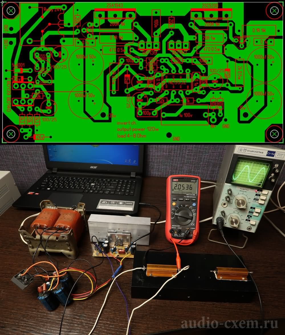
RMS 100W Amplifier Schematic Diagram
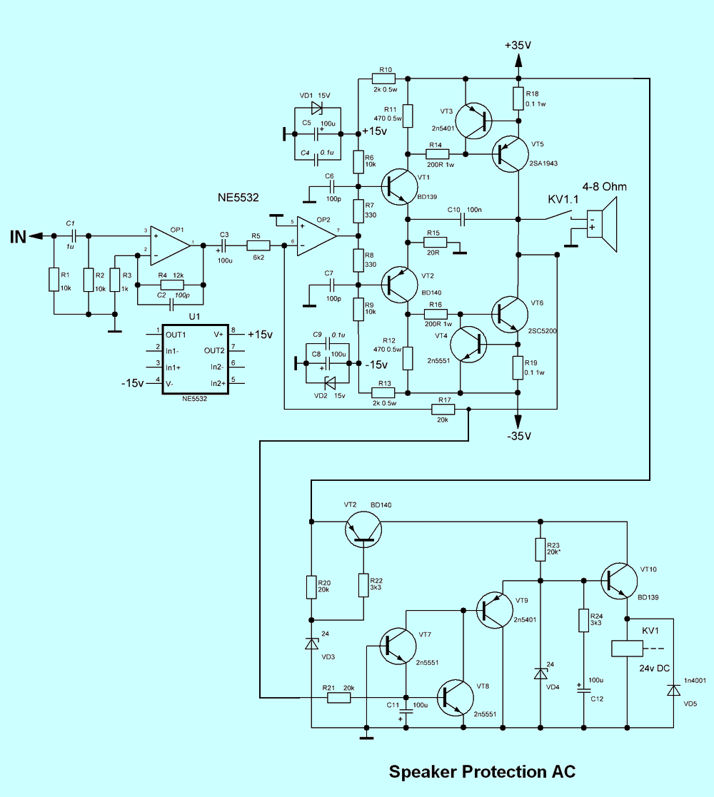
Stabilizer resistors R10 and R13 with a power of 0.5W, resistors R18 and R19 with a power of 1W, the rest 0.25W.
I installed 15V zener diodes (VD1 and VD2) 1N4744A, and instead of 24V zener diodes (VD3 and VD4), I installed 13V 1N4743A, respectively replacing the relay from 24V to 12V.
Instead of 2SC5200, 2SA1943, you can use TIP35C, TIP36C or another complementary pair that is suitable in terms of characteristics and pinout.
Transistors VT5 and VT6 must be installed on a radiator with a surface area of at least 1000 cm 2 . It is necessary to install a dielectric gasket between the radiator and the transistors, this is not necessary if the amplifier case is plastic, since the collectors are already interconnected according to the scheme, but for safety, I still installed them.
Alternative pcb, schematic download link;
Source: audio-cxem.ru/shemyi/usiliteli/na-tranzistorah/usilitel-dorofeeva.html


Zip file is password protected.
What is the password?
Hi,
pass: 320volt.com