The high-power control circuit motor reversing DC motor speed controller circuit features soft start, relay switching of motor direction, and PWM speed control. I have shared the circuit before. There are details in the article “High Power 30 Amp DC Motor Speed Control Circuit”, but I prepared a new article because I applied it and used it in battery motors. It was prepared in the PCB drawing.
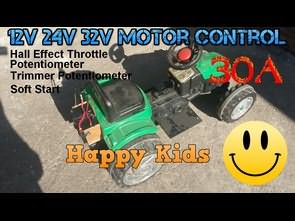
The motor driver circuit was controlled by the throttle lever with hall effect sensor on the 3-wheeled motorcycle for children. The other circuit was used for the control of the engine and installation removed from the non-battery scrap ATV and the tractor converted to battery.
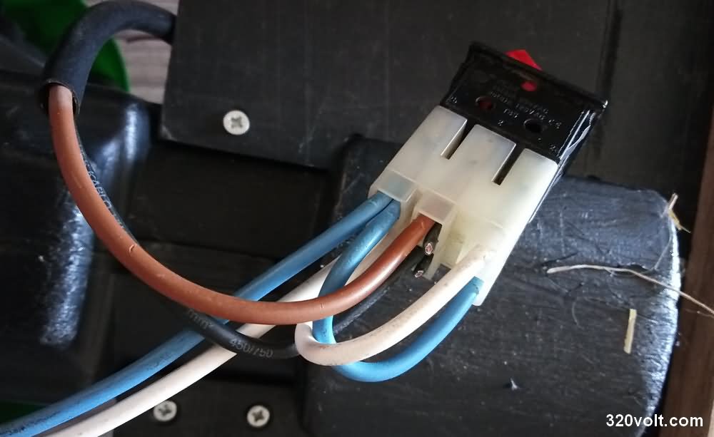
The trimpot in the motor driver circuit was adjusted slightly lower than the full speed, and a piece of wood was placed to put the feet and the push-release switch used in electric sewing machines was connected to the right foot, this switch is connected to the section that says LCK. Other circuits were used on ATVs for kids and similar battery powered bikes.
Video About Test and Details

Summary Description of Motor Driver Circuit
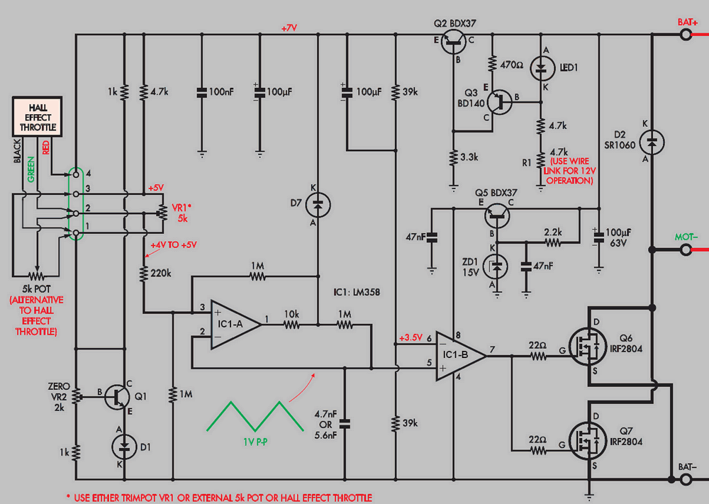
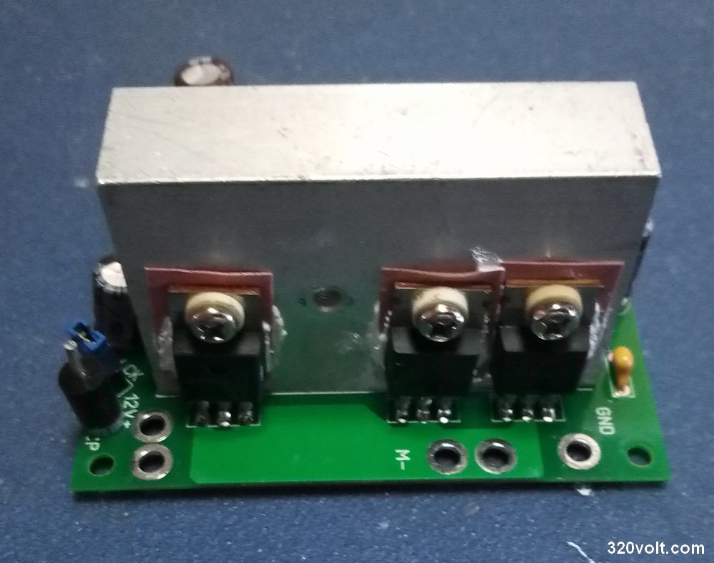
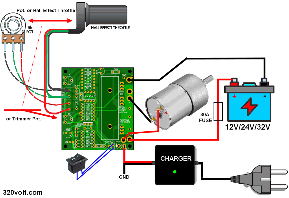
The motor reversible DC Motor Speed Controller uses a pair of high power MOSFETs connected in parallel to drive the motor. It can work with voltages from 12V to 32V, currents up to 30A.
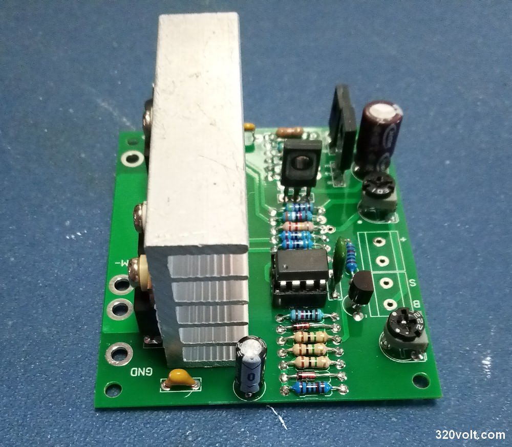
Relay switching circuit is logic control, it only changes direction when the motor is stopped. The unit has two floors. the first is basic speed control with two parallel MOSFETs and a pair of op amps to provide pulse width modulation (PWM).
The second floor is the relay motor reversing circuit. If you don’t need the motor reversing feature, you can just use the driver stage. Speed control can be via a built-in trimpot, an external 5k potentiometer, or a motorcycle throttle based on a Hall effect sensor. Motor Drive Circuit Can be used for wheelchairs or electric bicycles.
The LM358 op amp and related components form a triangle wave oscillator. Its frequency is around 300hz and output amplitude is around 1v from peak to peak. The average DC level of this triangular waveform can be raised or lowered depending on the setting of the 5k speed control potentiometer. This output waveform is connected to the non-inverting input of IC1-B, pin 5. The IC1-B is connected as a comparator and compares the triangular waveform with the 3.5v fixed reference on pin 6.
When the speed control is advanced such that the peaks of the triangle waveform at pin 5 exceed 3.5V, the peaks of the triangle exceed the reference voltage of 3.5V on pin 6 of the waveform at pin 5, the output at pin 7 rises and turns this power on.
soft start soft start
When voltage is first applied to the controller circuit, the 100μf capacitor on pin 6 of IC1-B discharges then starts charging through the 39k resistors on pin 6, thus pulling the voltage at pin 6 to 3.56. therefore, at the moment of power up, the engine cannot start even if the throttle is fully advanced.
This gives the circuit a soft start feature and prevents the engine from starting with a jolt at the first startup (running about 3…5 seconds late).
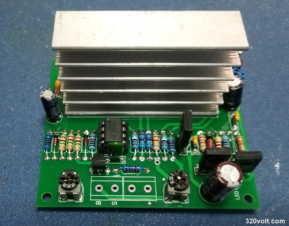
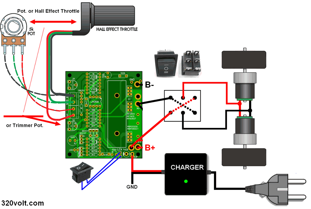
Motor Reversing Relay Switching
DC motor speed controller has additional circuit with relay to change motor direction. For currents between 5A…20A, double contact switches can be used as I mentioned in the article “Reversing the dc motor with a two-position switch”, but relays are required for higher currents. It can be done with a single large dipole reversible (DPDT) relay, or it can be done by switching two single pole reversible (SPDT) relays simultaneously. The control of the relays in the circuit is made with the CD4093 quadruple 2-input Schmitt trigger integrated, the motor direction is changed with the button, and there are also led indicators.
I added a charge diode and inputs for on-off to the motor driver I use. On the module I mentioned, the battery is charged via a 3 amp diode, so this diode is required to use the original charger. I used this part for the accelerator pedal.
If you are going to run the circuit with 12V (battery or adapter), you do not need to use the 5K tirimpot on the board, if you are going to use an external 5K Potentiometer or throttle with hall effect sensor, which will be wired instead of R1 4.7K resistor. Throttle lever with hall effect sensor for VR2 (2kΩ) trimpot zero adjustment
When I used it, the motor was spinning from a light position even though the handle was not turned. I used 2.2k since I don’t have a 2k trimpot.
Since I don’t have IRF2804 mosfet in my hand, I used IRF3710 mosfet, since the first motorcycle’s power was not high, I used IRF3710 in the tractor, no problem, if you can, use IRF2804 mosfet. RDS(on) resistance is 2.0mΩ current 75A IRF3710 mosfet’s RDS resistance is high 23mΩ current is IRF1405, IRFB3607 instead of 57A IRF2804 mosfets can be used. I used BD139 instead of BDX37 transducers.
Finally, this type of motorcycle uses YK31 series motor driver in the voltage range of 12V, 24V, 32V, 48V and has models between 250W, 350W, 500W, 800W according to the number of mosfet and diode power. I repaired a few of these modules and started the motors and used this circuit instead of the burned cards.
Source: http://www.siliconchip.com.au/cms/A_112070/article.html
PCB file of 30A Motor driver circuit 28469a.zip password: 320volt.com


