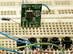
5 Channel RF relay control circuit 433mhz RF module set based on PIC12F675 microcontroller IC can be used (I used 434mhz module set, no problem) Depending on the RF module quality and the antenna used, it can remotely control the relay between long distances and can be used for turning on and off various devices and for different tasks.
The protocol transmits 4 bytes, 2 bytes of any serial number that should be used in both tx and rx. In this case, the number 0x89ab is used. The next byte is a copy of the gpio that shows the status of the keys being typed. And finally, the last byte is the sum of the first 3, which serves as a check for the integrity of the transmission.
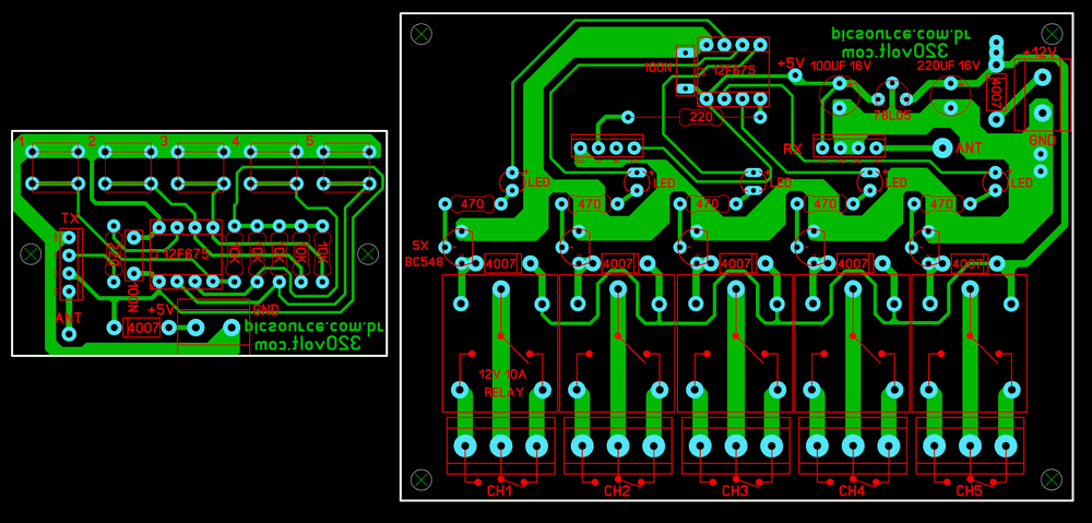
Press release or hold mode can be used by changing the receiver software. A 12V 10A relay is connected to the outputs of the PIC12675 Microcontroller. You can edit the PCB file for a more powerful relay. The operating voltage of the RF Receiver circuit is 12VDC, if the receiver is 5V
RF Relay Control Circuit Diagram PCB
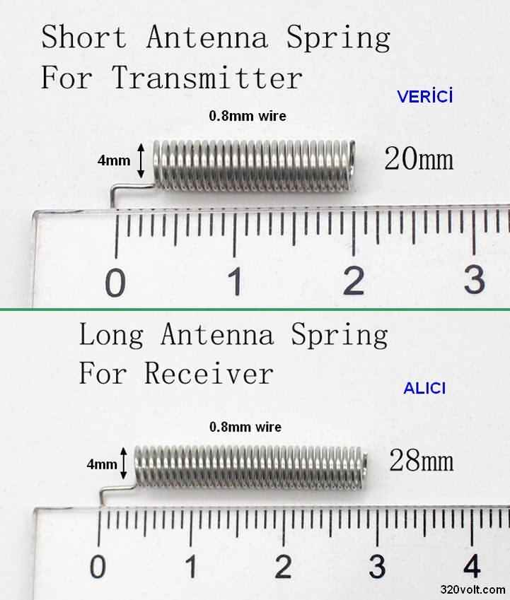
Making RF Module Antenna
RF module kits are sold with the antenna, if you do not have an antenna, you can make an RF module antenna according to the measurements below, generally the wires in the ethernet cable are used. You can use insulated transformer wire.
RF Transceiver circuit PCB and code files; 28570a.rar password: 320volt.com


