A motor driver circuit designed specifically for robotic projects using high power collector motors, with or without PWM modulation with a Microcontroller or debug card, to fully control two motors. The drive is made with a symmetrical dual channel digital controlled circuit. It allows you to change the axis rotation direction independently for two motors, with the help of PWM modulation, you can change the rotation speed in any direction. The circuit design drive consists of a control digital part made in high-power fetuses, fet drives and two symmetrical bridges. The design load capacity of the drive is up to 19A.
Each of the connectors has two sections and has a stamped numbers 1 and 2 on the case. Figure 1 is marked with the mounting input, which causes the rotation direction of the motor shaft to change. When sending the diary. 1. the motor shaft will turn to one side while feeding the log. 0 to the other. Turning in one direction or another will only occur if there is a log at the input 2 of the connector.
You can change the speed of rotation of the motor shaft by changing the pulse width of the PWM signal. To stop the rotation of the motor shaft, you need to give a zero level PWM signal. If the PWM signal is not planned to be used, the control of input 2 can be carried out at logical levels. For example, a 1 Input 2 motor spindle returns the maximum speed. 0 input rotates 2 motor spindles.
Caution: Before changing the direction of rotation of the motor shaft, programmatically set a short pause to prevent current bumps in the bridge driver! And only after that 1 Change the login status.
For braking, it does not matter what the logic level at input 1 is. It is enough to put a logical zero at the input of the 2 connector.
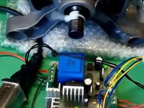
Motor Driver Circuit Diagram
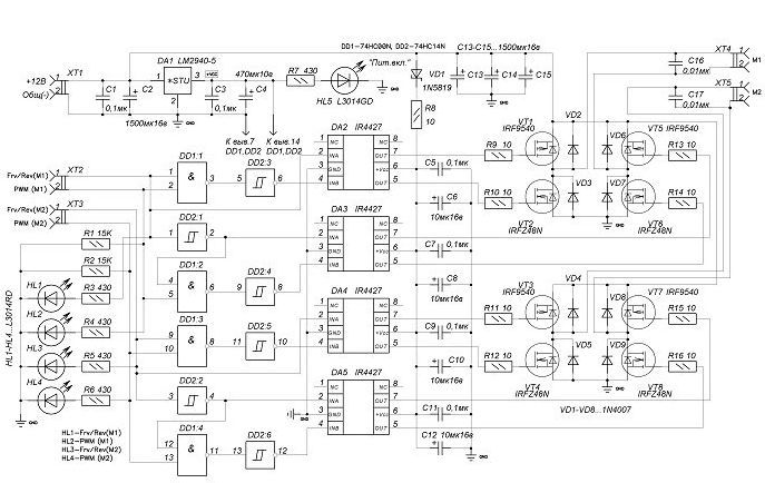
All signals on inputs 1 and 2 of the xt2 connector are displayed on xt3 red light leds. If any of the inputs have a high level signal (log.1) then this corresponding LED lights up. If any of the inputs have a low level signal (log.0), the LED goes out. The green LED indicates the presence of a +5 volt supply voltage to the digital chips DD1, DD2 (74HC00, 74HC14).
It is not necessary to connect the motors to debug the drive control program, it is enough to monitor the passage of the command to turn on the corresponding LED. The logic unit corresponds to the lit led. Logic zero corresponds to the extinguished led.
For Xt2 connector, log.1 Inlet 1 glow HL1, log.1 Inlet 2 glow HL2.
For Xt3 connector, log.1 Inlet 1 glow HL3, log.1 Inlet 2 glow HL4.
The motor driver has its own power supply with an output voltage of +5 volts. This voltage is generated by the LM2940-5 regulator. Using this chip improves drive performance and prevents the logic portion of the circuit, the voltage and de-energization of the transistor control circuits when starting motors.
Discharge capacitors When one or two motors are turned on, the batteries are subjected to a significant load as a large current flows. The drive board C2, C13, C14, C15 (1000uf) has high capacity capacitors to provide primary current pulse in the motor winding and to discharge the batteries. Capacitance must be related to the allowable load current for the motors used. Exact dimensions of the pcb: 100x80mm.
source: nickhome.ru/electronic/schems/
FILE DOWNLOAD LINK LIST (in TXT format): LINKS-26772a.zip


Circuit de commande de moteur de 19 A pour des projets de robot puissants
Un circuit de commande de moteur conçu spécifiquement pour les projets robotiques utilisant des moteurs de collecteur haute puissance, avec ou sans modulation PWM avec un microcontrôleur ou une carte de débogage, pour contrôler entièrement deux moteurs. Le variateur est constitué d’un circuit contrôlé numérique symétrique à deux canaux. Il vous permet de changer le sens de rotation de l’axe indépendamment pour deux moteurs, à l’aide de la modulation PWM, vous pouvez changer la vitesse de rotation dans n’importe quelle direction. Le variateur de conception de circuits se compose d’une partie numérique de contrôle constituée de fœtus de haute puissance, de moteurs de fets et de deux ponts symétriques. La capacité de charge nominale du variateur peut atteindre 19 A.