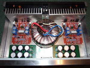
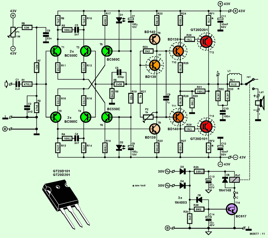
GT20D201 (p-channel igbt) and GT20D101 (n-channel igbt) are used on the output stage of the amplifier circuit with IGBT transistors. A high quality amplifier circuit is also very stylish in its printed circuit design. Drawings about amp boxing layout plan and chassis are given.
IGBT transistor amplifier circuit can deliver 88W with 8 ohm speaker and 167W RMS real power with 4 ohm speaker. Noise (THD Total Harmonic Distortion) level is very low 0.002% (1khz) input impedance 47.7k. input sensitivity 1.1v
The quiescent current adjustment is made with the P2 1k trim pot. The P2 trim pot should be adjusted so that the current drawn by the idle speaker is between 100….200mA without inputting a signal to the amplifier input. A 2x30v ac 350w transformer can be used for the power supply supply circuit of the circuit.
DC Filter capacitors 4x 10.000uf 50V Rectifier bridge diode metal type 35A ones. After rectification with a bridge diode, it becomes 2x43v dc. There is a high voltage of 86v in total, be careful, this value is dangerous.
In addition, the speaker has a delay circuit, it takes its supply from the same transformer, be careful, AC 2x30v goes to the delay circuit. This circuit, which is added to the slow start circuit for the power supply stage, provides protection against sudden loading of the transformer and capacitors. Output coil will be wound 8 turns of 1.5mm wire
IGBT Transistor Amplifier Circuit Diagram
Brief summary information about IGBT Transistors (http://en.wikipedia.org/wiki/IGBT)
Consisting of the initials of the word Insulated, Gate, Bipolar, Transistor, this electronic circuit element behaves like a mosfet while driving, and acts like a bipolar transistor (high current) when it works (voltage controlled).
You can use it like a diode that you can turn on and off with the help of a circuit, like a triac that you can control with the gate end, or a mosfet transistor that you can control with the gate.
160W IGBT Amplifier Circuit pcb schematic:


Microcontroller Controlled Digital Power Supply Circuits Archive
NXP80C31, PIC16F876, PIC12F629, PIC18F452, PIC16F876, PIC16F870, PIC18F252, HC908QT4 made with integrated power sources in various voltage and power
MCU of microcontrollers in power electronics used always been interested 🙂 Unfortunately this type MCU, PIC, ATMEL a controlled power supply did not do it to do Yade get the idea people who want a few examples MCU controlled digital power supply has a project.
Digital Power Supply Example
160W IGBT Verstärker Schaltung
Anfi-Schaltungs-Endstufe GT20D201 (p-Kanal IGBT) und GT20D101 (n-Kanal IGBT) verwendet eine ganzheitliche Verstärker Schaltung Leiterplatte Design auch ziemlich stilvolle Schaltung 8 Ohm Lautsprecher mit 88W 4 Ohm Lautsprecher mit 146W RMS reale Macht kann Rauschen ( THD Total Harmonic Verzerrung) Ebene ist sehr niedrig 0,002% (1kHz) Eingang Impedanz 47.7
Die Ruhestrom-Einstellung erfolgt mit P2 1k-Trimm-Pot-Verstärker-Eingangssignal ist im Leerlauf, bevor Sie den vom Lautsprecher gezogenen Strom zwischen 200 und 100 … eingeben. P2 Trimmkanne sollte eingestellt werden. Schaltkreis der Stromversorgung Schaltung für Ressourcen-Entdeckung 2x30v 2x43v nach Gleichrichtung Diode Brücke Transformator kann 350W AC DC Hochspannung 86 V Insgesamt wird es vorsichtig sein, ist dieser Wert-Hander.