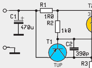
The current limiting circuit shown in the diagram , especially as the drive power LED driver , this circuit can be used … Easy to use and inexpensive , keeping a constant level of output current regulator prevents damage . When a problem occurs on the transistor T1 circuit on the power consumption would be approximately equal to the input voltage . According to the circuit diagram of feedback resistor R4 to protect the transistor T1 with an additional current limiting circuit which is used.

Under normal circumstances, transistor Q2 is not my message . R1 and R3 resistance MOSFET T2 feeds . Outputs when overload occurs through transmission T1 , T2 applied to the back of the MOSFET and thus diminishes the resistance between drain and source increases , so current limiting occurs. The situation described here, the two outputs (X1 and X2 ) is a condition that applies to . Circuit should be the same as the input voltage output voltage regulator circuit was not so you can not 12v or 12v to 20v enter you can not enter the 5v or 12v to 12v 600mA 12.5V to the circuit if internal 5.5V or 5V 5V can be given ..
Published: 2012/01/26 Tags: power electronic projects, simple circuit projects
Development Circuit STM32F103RBT6 QFP64
STM32 Arm projects, you can use the dimensions of the printed circuit card a useful development circuit is quite small and single-sided snow on the USB I2c links to reset the input outputs RS232 SWD, etc, you have to boot the buttons have a circuit diagram and pcb artwork in addition to the picture format That has the source drawings with Cad program.
Durch die Strombegrenzungsschaltung, die im Diagramm dargestellt ist, kann diese Schaltung verwendet werden, insbesondere als Treiber für die Ansteuerungs-LED. Sie ist einfach zu bedienen und kostengünstig und verhindert Beschädigungen, indem der Ausgangsstromregler konstant gehalten wird. Wenn ein Problem an der Transistor-T1-Schaltung auftritt, wäre der Stromverbrauch ungefähr gleich der Eingangsspannung. Entsprechend dem Schaltbild wird der Rückkopplungswiderstand R4 zum Schutz des Transistors T1 mit einer zusätzlichen Strombegrenzungsschaltung verwendet.