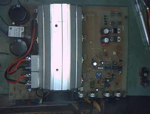
Very strong power supply high power devices circuit to run the ideal voltage and current settings accurately can be done over-heat protection temperature fan control features used power transistors tip142 npn darlington toroid transformer used this transformer lighter and becomes more efficient, but the prices are high normal hair transformer used in
0-30V 0-10A Power Supply Project


With an infinitely adjustable voltage from 0 to 30 V, up to 10 A output current, a high-fan engine as well as excellent properties usually have it PSU board hardly be desired.
Output : 0 – 30 V
Output current : 0 – 10 A
Internal resistance
Voltage : infinitely, coarse and fine
Electricity : infinitely, coarse and fine
LED indicators : U-control, I control,
High-cooler unit with secure electronic fan control
Over-temperature protection circuit
PCB dimensions : 235 x 186 mm
Integrated circuits used in power supply and transistor information
KBPC3504
2N3019
CD4011
7805
7905
LM358
BC548
BC558
TIP142
Kayank: lea.hamradio.si/ 0-30V 0-10Amp Adjustable Power Supply PCB schematic alternative link:


LED Display Speed Meter Circuit with AT89C51
Speed Meter Circuit consists of four parts. These Supply solid floor Sensor sensor, microcontroller and microcontroller solid hexadecimal numbers we obtained from the 7-segment display technology with time code converter solid. Program Keil µVision3 AT89C51 microcontroller.
Supply DC 12V working with solids. However, by 7805 we have achieved solid display technology and microcontroller is supplied with 5V regulated. 12V opam the feeds OPAMPs from sensors to information received by the comparator works as and with the potentiometer we determine the reference voltage sensors have achieved with voltage compare output 0-12’re getting 12V to microcontroller directly would not go zener 5.1V a fix and this information logic 5V and 0V used it as we are .