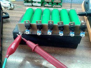
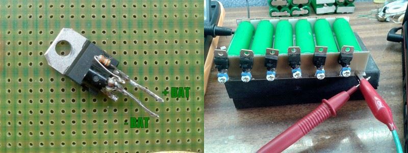
Compared to the previously shared Li-Ion battery balancer battery balance circuits, it is a simple circuit that you can make with less material. Li-Ion battery stabilizer is a system that controls the voltage of each cell/cell section and does not allow the charging voltage to be exceeded. If one of the cells is charged earlier, the stabilizer takes the excess energy and loses it in the form of heat, preventing that cell’s charge voltage from being exceeded.
If we connect several Li-Ion batteries in series and charge them without a stabilizer, it is certain that one or more of the batteries will fail over time. Batteries have different internal resistances and capacities. Li-Ion chemistry is unstable and can reach high temperature and explode when overloaded.
For details, in the article “Battery Balance Circuit for Balanced Charging of Li-ion Li-polymer Batteries”
The TL431 is a regulated zener diode. The circuit is completed by adding a power transistor that can give 100mA under continuous load. Resistors R1 and R2 set the voltage to 4.20V. At the limit of 4.20V, the system will start to open the transistor so as not to exceed the set voltage. The minimum voltage increase will cause the transistor current to increase very quickly. During the tests, already at 4.22V (exceeding 20mV), the current was over 1A, so this result is very satisfactory.
Any PNP transistor can be used in voltages and currents that serve our purpose in the selection of transistors. If the cells are to be charged with 500mA current, the transistor current should not be less than this value and its coefficient.
No less than the power we will dissipate on the Pd factor (power loss), the transistor will be a heater and will lose excess energy in the form of heat. Simple calculation. 4.20V * 0.5A = 2.1W power dissipated on the transistor. For currents of 1A or more it will require some cooling.
During testing, I checked a handful of bounce-back transistors. BD244C, 2N6491, A1535A and system all behaved the same. I even tried the BC327 and it worked perfectly with 500mA current although not suitable
Simple Li-Ion Battery Balancer Circuit Diagram
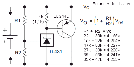
R1 and R2 must be selected to obtain the limiting voltage resistors calculated from the formula in the diagram. Using a 0.1% tolerance resistor will work fine.
Check the reference voltage before mounting the system in the cell, practice shows that even though we use the correct resistors calculated from the formula, there will still be a small error of 20-50mV. In addition to the resistors, the tolerance of the TL431 zener is also a factor in the internal resistance. A multi-turn trimpot can be used for fine tuning.
What voltage should I set?
If the charger is cut off at 4.20V, we need to adjust the voltage a little higher. Chargers show 10, 20, or 50mV more voltage on the cell than it should, depending on the charger design. The charger detects the end of charge when, at a certain voltage, the charging current drops below 100mA, for example, depending on the charger design. If the stabilizer is set too low, it artificially increases the charging current when it starts, and the charger will never discharge. I think the safe voltage would be 30-50mV higher. If we charge the pack ourselves with a laboratory power supply, we adjust it to the sum of the stabilizer voltages to ensure that they do not turn on unnecessarily.
Source: mdiy.pl/bardzo-prosty-balancer-do-ogniw-li-ion/ the explanation in the article is taken from the source site.


Great idea.
Would it be even more simple to use Zener Diodes (if chaging power ist not too high), or let’s say 5 normal Si-Diodes in series (3,5V “cutoff” resp. bypass voltage)?
Zener diodes are not precise in their clamping voltage. The clamping voltage is dependent on current and temperature. The TL431 shunt regulator can have accuracy of ±0.5% depending on grade.
Hi, thanks for informations.