Adjustable microcontroller-controlled digital power supply project with all its details, volt and amperage values can be read on the LCD pcb box design 3D views There is source software prepared in c language. An applied project belonging to Elektor magazine.
Digital power supply This project is a power supply modification published by Osvaldo Valdorre’s elektor magazine number 260.
• Controlled ventilation according to current consumption.
• Current consumption reading with visual and audible overcurrent indication.
• Preset memories (2.5, 3, 3.3, 5, 9 and 12 volts at 0.5A, 1A and 2.5A).
• Ventilation control with temperature reading.
• Control circuit power supply lines separated from the power section.
• Information of all values via LCD 16×2 with contrast control and backlight.
• Control and communication via RS232 with PC or another control card.
• Code written in C for the SDCC compiler.
A power supply is one of the most used tools in an electronics lab, with various voltages (12v, -12v, 5V, -5V) high amperes on the market.
The idea of this power supply is that it is an analog source controlled/regulated by a microcontroller, easy to install, inexpensive, and has multiple features with expansion possibilities.
Design constraints Forced ventilation must be controlled with temperature and consumption as heat dissipation for 25V at 3 or 4A can compromise some components.
External power lines should be separated from the control section, this will reduce possible voltage drops from the use of ventilation, LCD backlight or other devices.
The weight of two transformers plus electronics in general can cause the source to have a significant weight (3kg in my case), so a 3mm aluminum cabinet will be used.
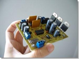
The circuit consists of two parts, one of which is analog with a stepper transistor, LM324N is in working condition, transformers, 7805 regulator, control inputs and outputs.
The control part consists of the microcontroller, LCD, buzzer, ICSP connector, and connectors to the input buttons and encoder if selected to be used.
The regulator circuit is dominated by the LM324N component; this is a quadruple operation that gives us a maximum voltage of 32V and the possibility of using low tolerance resistors (in my case I use 5%, but 1% is recommended). I divided the circuit into sections for better understanding and analysis.
• Input voltage: 220VAC
• Output voltage: 0 25VDC to 0 2.5A
• Display Accuracy 1V / 100mA 100mV / 3mA
• 2×16 LCD volt ampere display
• RS232 Communication
• Heat fan control
• Short circuit current control
Digital Power Supply Test
A power supply is one of the most used tools in an electronic laboratory, on the market of various types, with fixed voltage, adjustable analogue, switching power supplies (such as PC) that provide varying voltages (12V-12V , 5V,-5V) with higher amperage. The idea of this power supply is that an analog source is controlled / regulated by the microcontroller easily assembled, inexpensive, feature rich with possibilities for expansion. Since heat dissipation 25V 3 or 4A may compromise some components must have forced ventilation and temperature controlled consumption.

External power lines must be separated from the control part, this reduces any voltage drops due to the use of ventilation, LCD backlight and other devices. To facilitate the construction PCBs will be designed to face without bridges without impeding the use of lower cost methods such as heat transfer toner. The weight of two transformers more electronics in general can lead to the source has an important weight (3kg in my case), is why a 3mm aluminum housing is used.
The programming language must be C since it is easy to understand for the vast majority of people, but with assembler routines when required execution efficiency.


The circuit consists of two parts, one with analog pass transistors, operational LM324N, transformers, controller 7805, inputs and control outputs. The control part consists of the microcontroller, LCD, buzzer, ICSP connector and connectors for input and encoder buttons if you choose to use. Analog part The regulator circuit is dominated by the LM324N component, a quadruple operational that gives us the possibility of a maximum voltage of 32V and the use of resistors low tolerance (in my case I use 5%, but it is recommended 1%).
source sergiols.blogspot.com/ PIC16F877 Adjustable Digital Power Supply Circuit schematic pcb code files Alternative link:
Password: 320volt.com
Published: 2009/05/05 Tags: microchip projects, microcontroller projects, pic16f877 projects, power electronic projects, power supply project
Multi-Purpose Picmicro Test Boards
18 pin 28 pin 40 pin microcontroller series for a very pic usb rs232 multi-purpose development, test circuit ISCP has links with the on-board outputs can be connected upside additional apparatus has all the pcb files
The Picmicro Test Boards uses a PCI socket and even had an old PC to tear desoldering it, build super plate Nocturne and then solder the socket made me ponder a compromise, but flexible, which serve with little exfuerzo for common PIC (8, 18, 28 and 40 pins for example) through the socket to pin connector. Thus was born the Multiboard distributing connector ports in 4 combs 12 each, the first would have common inputs and outputs and the rest would be used or not according to CIP.