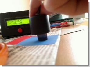
This circuit using a PIC 16F877 microcontroller LCD (Liquid Crystal Display) has been applied on the color sensor. For circuit design and printed circuit board operations and Proteus ISIS Proteus ARES program is used. The operating logic circuits in a closed environment in order of ARD flashing light emitted from the LEDs is based on the influence resistance to change.
PIC16F877 Microcontroller Color Sense Project


LDR placed in front of the light reflected from the object generates an analog signal with the effect of this signal microcontroller 16F877 ADC PORTA.0 from pins to entering the measurement is made. This circuit is previously determined LD colored cardboard placed in front of each color has its own signal table is deleted.
LDR Connection

LDR as shown in the middle of three LEDs to be soldered to phenolic hole is made and resistance connections. Then close the circuit to the sensor panel of any box cover, etc.. and LEDs to close around a triangle is black colored cardboard.
NOTE: Circuit ldren in parallel to the signal cable from the LEDs if you put a value close to this value you can find. Values in this way, but I try to find the resistance less than 330Ω resistor is not in my hand was making a very small value led me hooked 🙂


Circuit of the microcontroller code “microcode Studio Plus” “PicBasic PRO” and has been compiled compiler written in. For compiling files on your computer, the compiler must PBP246 and MPASM assembly.


All files belong to the color sensor with PIC16F877 isis circuit simulation software ares pcb and source files PicBasic pro:
Password: 320volt.com
Special thanks; Mine Cüneyitoğlu and ETE
Published: 2009/04/07 Tags: microchip projects, microcontroller projects, pic16f877 projects, picbasic pro examples
LCD Stopwatch Countdown Counter Circuit with PIC16F877 Picbasic Pro
This circuit using a PIC 16F877 microcontroller LCD (Liquid Crystal Display) application was made on the stopwatch and countdown. Counting the TMR0 interrupt for the microcontroller is used. For circuit design and printed circuit board operations and Proteus ISIS Proteus ARES program is used. Flow diagram of the circuit is as follows.
Countdown Counter Circuit