The advantages of lithium batteries are many, first of all, high power, low weight and no “memory effect”. Also, a lithium battery has three times the voltage of a nickel-cadmium or nickel-metal hydride battery (1.2V). However, lithium batteries cannot be used safely and efficiently without special control systems. The first version of the Li-Ion Battery Protection Circuit is designed to protect the 8.4v battery pack with serial connection. It provides protection against discharge and short circuit.
First of all, I will talk about the first version of the circuit.
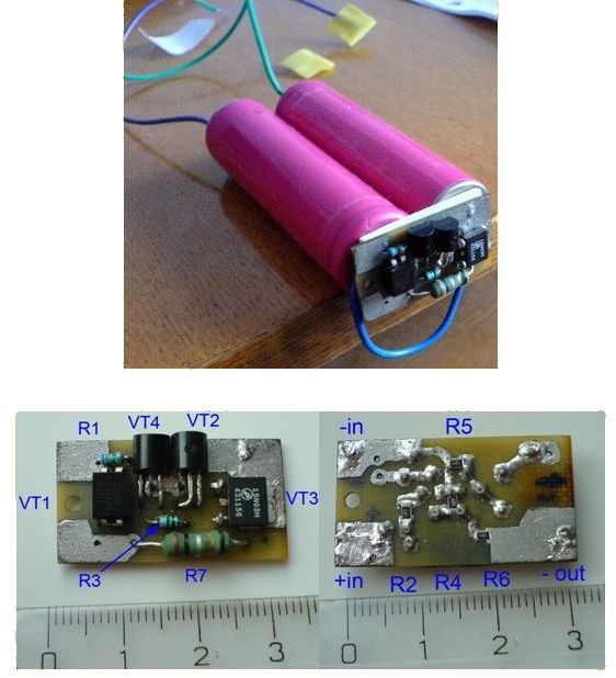
Normal operating mode: When a battery pack consisting of two charged batteries (8.4V) connected in series is connected to the circuit, the transistor VT4 KT3107 opens. Due to the current flowing through R4, the voltage at the VT4 KT3107 emitter is about 0.7V. Also, resistor R4 keeps 2SK583 VT2 closed.
Over-discharge protection: When the voltage on the battery drops to 6V (3V per cell), the voltage across the divider resistors R1-R2 drops, the voltage at the IRFD9020 VT1 gate pin also drops to the shutdown threshold, the VT1 IRFD9020 turns off. The VT3 APM3055 is connected to the “-” terminal of the battery via R6, so the VT3 APM3055 will also turn off. The load is disconnected. In order for the system to return to normal operation, you must disconnect the load and charge the battery.
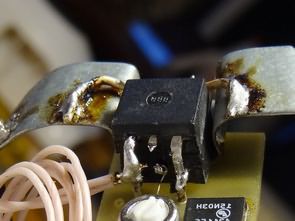
Short-circuit protection: The short-circuit current is set by R7. The smaller its value, the more current the circuit gives. With a 0.1 ohm resistor, it allows current up to 4A, more current is considered short circuit. When operating at high currents, resistor R7 must have sufficient power of at least 1W.
In the first version of the circuit, since the short-circuit protection does not normally work in capacitive loads with instantaneous high current, the modified R6 was increased to 330 kOhm and a 0.1 uF capacitor was added in parallel to R4. The disconnection of the load is delayed by about 3 ms. The new circuit worked for six months. There have been no problems.
In the event of a short circuit, the circuit switches to current source mode for 3 ms. At R7=0.05 Ohm, the short-circuit current is 8 A, the overcurrent protection is triggered at 4 A. Thus, the circuit is guaranteed to work on capacitive load.
8.4V Battery Protection Circuit Diagram
Lifepo4 Li-Po Li-Ion Battery Protection Circuit
Over the years, the circuit has been modified many times, tested in different conditions. The main difference of the new version is its modularity, the ability to control each battery in the package, set parameters to protect the battery.
Due to its modularity, the circuit can be configured for any number of cell batteries. It was decided to limit it to four batteries because 4 series or less are most commonly used at the moment.
When the battery or battery pack is connected, the voltage on the capacitor C1 (and on the VT5 base) is close to zero, VT5 is turned off, plus the positive of the battery goes from the R10 to the VT8 gate. It connects the load to the minus of the battery.
The S1 switch allows you to manage a strong load. Screwdrivers, cordless vacuum cleaners, etc. because it is very important for When operating such a load, instantaneous high current draw, which is considered a short circuit by the circuit, inevitably occurs. The current through S1 does not exceed a few microamps, so you can use various pushbuttons and other low-current switches. It can also be done on thin wires away from the motherboard.
Operation of the circuit at full charge: The minimum operating voltage is determined by the battery type. For Li-Ion and Li-Pol min. level is 2.8V. For LiFePO4 it is 2V. 100k tuned resistor R7 is the same for all types.
When the voltage in one (or several) batteries drops to 2.8V, the VT4 base voltage, current, and collector current decrease, and the collector voltage increases. C1 starts charging. As soon as the voltage at C1 (base VT5) reaches 0.5V, VT5 opens, the gate voltage of VT8 drops. The voltage of VT8 increases (according to the source), which leads VT5 to open and VT8 to close. The load is disconnected from the battery. To bring the circuit back to normal working condition, you need to disconnect the load and charge the battery.
Maximum current at load and short circuit operation: Overcurrents occur not only during short circuit, but also when operating under intense energy-consuming loads (electrolytic capacitor during charging, motor with high current draw at start-up, etc.).
The load current creates a voltage drop across R15 connected to the VT7 base via R14. If the current exceeds the limit value (set by R15), VT7 opens. The gate voltage of the VT8 drops, the VT8 switches to current source mode (the current is kept constant even during a short circuit). VT8 voltage increases C1 starts charging via R13. If the current surge is short-lived (for example, with the engine running), the voltage drop across R15 decreases, VT7 closes (VT5 remains closed), VT8 opens.
If the current does not decrease, after a certain time VT5 opens, VT8 closes, the circuit disconnects the load from the battery. The delay time is determined by the C1 value. The current limiting mode is short-lived, there is no possibility of overheating of the VT8.
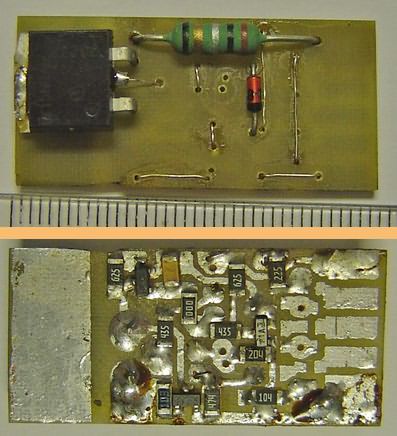
For SMD PCB: SMD transistors in SOT23 package: VT1-VT3 – 2SA733; VT4, 5, 7 – 2SC945 or equivalent. Any N-type mosfet in the VT6 – 15N03, TO251 or TO252 package with a threshold voltage of 1 – 3V.
Any N-type mosfet with a threshold voltage of 1 – 3V can be used instead of the 06N03L in the VT8 TO262 or TO263 package and should have 2 – 3 times more current than the short circuit current.
For DIP PCB: transistors VT1-VT3 – 2SA733 in TO92 package; VT4, 5, 7 – 2SC945 or equivalent. VT6 – 15N03 or equivalent in TO251 or TO252 package
In the VT8 TO220 package – 06N03L or any N type mosfet with a threshold voltage of 1 – 3V and a maximum current 2-3 times greater than the short circuit current. Two mosfets are connected in parallel for more power.
I think it is better for all resistors to be 1% tolerant except for the current limiting resistor, but the author said that resistors R2 and R5 should be 1% tolerant.
Because the author used a jumper instead of the trimpot R7, which is used to set the voltage cut according to the battery type and number. R6 has been determined exactly according to the desired voltage value.
The short-circuit current is approximately 2 times the operating current. R15 value is selected according to the short circuit current R15 = 0.5 / Current For example, the working current of the vacuum cleaner is 15A. Current = 25A R15 = 0.5 / 25 = 0.02 Ohms. Wire can be used for very small value resistors. The author used 2 wires with a cross section of 0.35 mm and a length of 250 mm connected in parallel for the vacuum cleaner.
PCB, Schematic alternative for all files 28534a.zip password: 320volt.com
Source: kosmopoisk72.ru


