I designed a new system using 16F876 as the advanced version of my project, which was previously published as an automatic charging system. When I say system, I made changes in the program without making too many changes in the electronics part. My previous system was working with 16C711 (once programmable) pic. In addition, I used the Negative Delta-V system to cut the current at the end of the charging process, that is, to understand that the battery is full.
Let me explain once again what Negative Delta-V means for those who don’t know. As NiCd and NiMH batteries are charged, their voltage increases. The voltage rise is interrupted after the battery is charged, and after this stage, there is a voltage drop of 10-20 mV per battery. For example, when 1 NiCd battery is discharged, it has a voltage of about 0.8V.
If you charge this battery, the battery voltage increases up to 1.7V at full charge. If we show this at the mv level, it’s 1700 mv. it goes around. From the moment of filling, this voltage drops to around 1680 mV. If you continue charging after this stage, the battery will start to overheat. This fallback is caught as a result of the measurements and it is decided that the battery is full and the charging process is terminated.
In the first system I did, the disconnection of the charge was based only on negative delta_v. However, I noticed that some (non-branded) batteries do not catch this moment of drop, or it is very difficult to catch. That’s why I also added voltage control to the system. As a result, the new program checks both the Negative Delta-V and the voltage of the battery and ends the charging process whichever it catches.
Another change was that the previous circuit was relatively universal. In other words, by connecting at least 2 batteries, it could charge up to 8 batteries in total without requiring any adjustment. However, when I realized that this was causing some problems, I decided to enter the number of batteries to be charged in the new program. Therefore, in the new program, you can charge a total of 8 batteries, provided that there are at least 2 batteries.
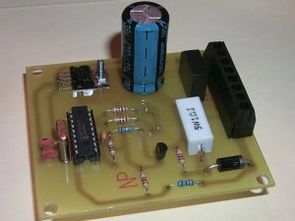
PIC16F876 Battery Charging Circuit


The above circuit 2 to about 8 AA batteries can charge up the battery pack automatically. Upon the first start of the program the SET button is pressed. How many battery charge by pressing the Set button will be entered into the program and the charging process is started by pressing the SET key again.
Evil is on the order of 700 mA current. Account logic is as follows;

However, the LM317 can provide a maximum current of 1 amp (1000 mA) are to be considered in the calculation of these values must be used with or instead of 3 amps.
Fast charging system is working with logic. In this case, 1 amp (1000 mA) batteries for about 1.4 hours, and 2.8 hours in 2000 mA battery can charge like. Operating logic of the system is as follows.
1, first check whether the circuit is connected to a battery. 2 volt battery on the values indicates the presence. Mind control status of the battery is empty before charging current is given over a period of 1 sec. This position is both LEDs off.
If the circuit is connected to the battery 2 in the battery for 30 seconds to stabilize. is taken to stand for.
In this position, the red LED is ON, the green LED is OFF.3 to about 4 minutes After this time 20% of the battery charge current is applied. In this position, the red LED is ON, the green LED flash is offline.
4 After this time the current is applied to the battery is fully charged. This position is both LED flash.
Following filling of the battery 5 to the battery 4% trichloroacetic called charge is applied to the charging stand. This ensures that the batteries remain connected as long as the discharge. In this position, the green LED is ON Red LED OFF.
Following the expiration of the battery charging voltage and current is automatically cut. Tepit of breakpoints in both negative Delta V charging system and eventually reach the required voltage of the battery is made by. In this system, after reaching a fully charged batteries continue charging the battery per case of 10 mV within a certain period starts falling. After allowing the battery to charge this fall should be discontinued. After this point to continue charging the battery case and will start to heat distortion will begin.
Circuit of the LM317 as current followers have been carried out by the method of attachment so that the charging voltage is adjusted automatically according to the number of batteries. Been tried with success is working with the entire circuit.

Charging circuit’s source PicBasic Pro and hex codes:


Sound Card Oscilloscope Circuits ADC0820
With a simple circuit running through your sound card oscilloscope circuits I’ve seen in many places on this circuit is running parallel port lpt ADC0820 circuit is simple and consists of a few passive components.
For the measurement of your windows program and source code are given. Be careful when testing circuit for any errors that may harm your computer motherboard circuit can not measure the high voltage of 2V vicinity there are limits