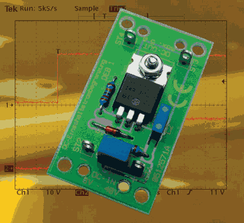
IRF4905 MOSFET with very few elements 5 amp current control, current limiting circuit input voltage line connected on 8 + .40 volts DC current through this circuit is limited to 5 amps 5 amp current draw on the output voltage drops
Even when loading medium capacitors in the range of some 1000 F µ Einschaltmoment flow in equal currents of 100 A and more. The dining Source Einschaltmoment before these high pulse flows to protect a tripping Fine upstream to prevent backups and high pulse loads of Capacitors to keep away, the DC-1 DEB Inrush current limitation Used.
To remedy this, you can switch to the Power supply of a large consumer Start control . This limited the The switch-on current to the extent that the circuit breaker does not trip , then the current limiting is automatically bridged , so that the consumer not in operation upstream of the Current limitation noted.
Just as it is this issue on the Are 230 V ac side , it is and device- internally to such high inrush currents. In electronic devices , mainly with the internal DC be supplied , here are usually Capacitors for high inrush responsible . At the power has A capacitor basically like a short circuit , the short circuit current of the
Mosfet Current Limiter
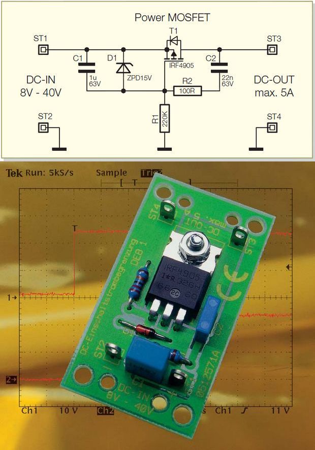
Source: elv-downloads.de/service/manuals/DEB1/61884-DEB1.pdf Mosfet Current Regulator limiter schematic pcb alternative link:


TDA7377 Amplifier Circuit (12V Stereo 30W)
A friend I made for 2x30W amp circuit to say the least, this work had to take care: D tda7377 was the best choice integrated single-source supply is working with 14 volt 2 × 20 watts of power can give max supply voltage of 18 volts DC passive elements very least three capacitors first resistance 🙂 Sprint Free to View and Print output was prepared with the layout found in the file, you can use Sprint Layout Viewer Program. (http://www.abacom-online.de/uk/)
TDA7377 with different links you can use as I’ve used 2x 3x 4x practices.
Bom. Preciso de esquema eletrónico de comando de slotcar com mosfet f44n.