Very nice Hi tech C examples we are here . In this application a variable defined as longer displayed on the screen that will examine how the number . tmp sequence numbers assigned to the same are shown on the display . The first button is pressed, the value of one variable increases, the second button is pressed, the value of the num variable is decreased by 1 , the last button is pressed, the num variable is assigned to 0 .
Num variable values on the display are divided into steps before the show . In a number of steps to get the mode field with 10% , ie, the number 10 and the remainder calculated tmp [0] in the first step of assigning a display is provided on the display .
Num variable to find them before the step 10 are divided by 10 mode and tmp [ 1 ] is assigned to the variable . Hundreds mode for the 100 to be divided by 10 and tmp [2] is assigned to the variable . By continuing this process, all steps such values can be calculated . Then the display () function is shown on the display with the contents of the array tmp .
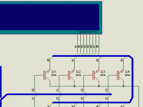
Variable number of display Circuit diagram

Application of the hi-tech c and isis files:


Button with LED Bar Control Hi Tech C Example
A button to connect to each pin of the microcontroller is not economical. If you are in the hundreds of computer keyboard and examined the inside of the foot, which was not integrated. Buttons with a vertical and horizontal connecting a column and row are generated.
Thus, the total number of columns and rows as columns x rows using pin buttons are easily controlled as multiplying the. 4 Shot with 4 rows of 16 buttons are checked. 8 rows of 8 Shot in developing applications with a little button you can control 64.
Button LED Bar control