The DIY version of the Crown XLS series professional amplifier is tried and tested and is even sold as a kit. There are 300W, 600W, 800W, 1200w versions that have been applied by removing some parts without changing the design of the original circuit much, I prepared a PCB for the 400W version.
Crown XLS amplifier technical specifications;
- Total Harmonic Distortion THD: 20 Hz to 1 kHz: 0.5%
- Operating voltage: + / – 80VDC
- Output power at 8 ohm load: 255Wrms
- At 4 ohm load: 400W rms
- Frequency response: 20Hz to 22KHz
- Input sensitivity: 1.25Vrms 400W rms
- Circuit gain: 32 dB
High-power versions of the circuit do not change much, just the number of transistors. In addition to the Crown XLS 400W amp circuit, I added the Speaker Protection Circuit that I shared earlier.
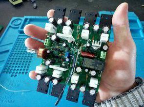
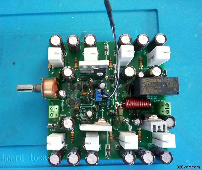
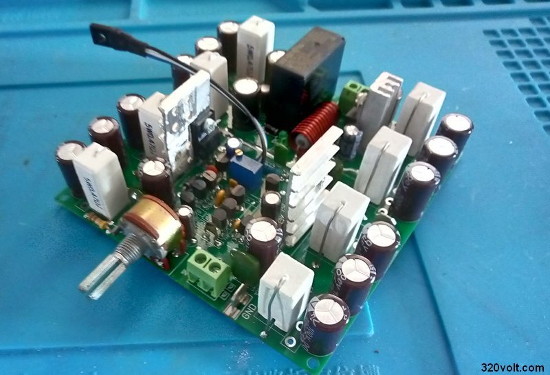
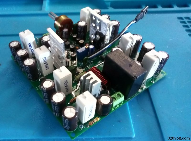
Most of the passive materials were used SMD type, so I fit both circuits to the PCB drawing of 100X100mm size. A potentiometer was added for sound adjustment. Arrangement was made for the signal chassis. Capacitors were added to the voltage inputs of the power transistors.
Crown XLS Clone PCB
Contents
Crown XLS Clone Amplifier Circuit Settings
For the first test, it is recommended to use a low voltage (2x35v….40v) in the amplifier supply, just in case, for the first test. If there is a high voltage at the output, there is a problem, check the circuit materials. If all goes well, the next step is to adjust the quiescent current. In the original circuit, a fixed 330-ohm modified circuit used a 360-ohm resistor, then they thought it would be better to adjust the 500-ohm trimpot.
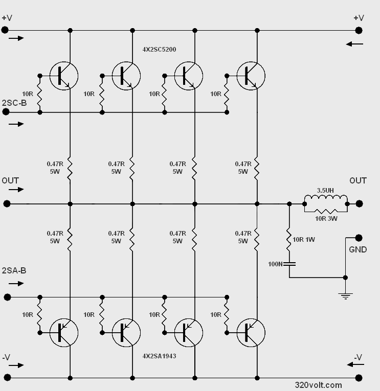
For the quiescent current setting, set the multimeter to the lowest DCV measurement range, measure the voltage drop across the 5W resistors. It should be around 30mv..40mv. If set too low the harmonic distortion is high, if set too high, the transistors will get very hot. (In the image file about the bias setting) MJE340 transistor will be mounted on the power transistor. An insulator must be connected to all transistors connected to the cooler.
It will be useful to reduce the noise if you make the grounding and power supply connection as in the diagram below. The part that says “Chassis” coming out of the star chassis will be connected to the amplifier’s case, and it will give good results if you use a complete aluminum case or an aluminum base case.
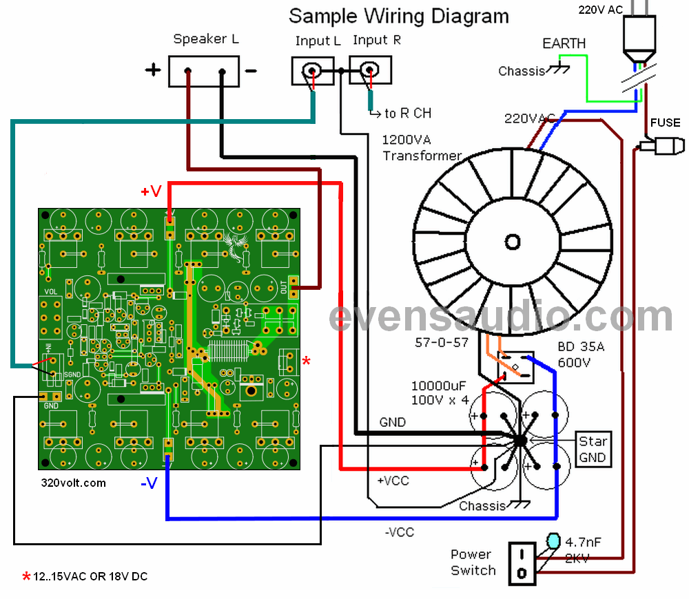
To operate the speaker protection circuit, 12v…15v AC or 18V DC voltage is required. If there is no possibility, you can operate it by limiting the resistor from the + plus voltage line directly, but if it will be used in the fan for cooling, external supply would be better because a very high power resistor will be required…
To operate the loudspeaker protection circuit from the main input voltage, the calculation of the limiting resistor will be as follows
Main voltage 80V (from + positive line)
LM7812 input 18V
Relay current 40ma
Resistance value calculation
80v – 18v = 62v
62v / 0.04 (relay current 40ma) = 1.550 1.5Kohm
Resistance power calculation
62v x 0.04 = 2.48 resistor power 2.48W recommended 3W
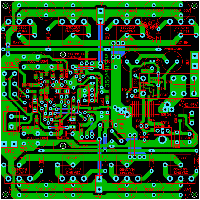
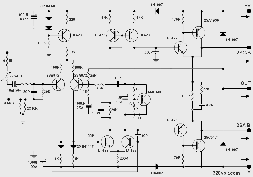
Crown XLS Clone Amplifier Circuit Diagram
In Crown XLS Amplifier circuit, all resistors except 5W, 3W, 1W and 10-ohm base resistors (1/4w) SMD 1206 sheath, it is better to use these resistors with 1% tolerance. I used 2SA733 transistors in the audio input, if you can find the original (2SA872) it would be better. Except for the BF series, the equivalents of the other transistors are written on the PCB.
Source: forosdeelectronica.com – evensaudio.com


Greetings… error in the original map posted… indicated in a red circle
https://ibb.co/g9y35Pf
Thank you for feedback. No errors on PCB. Circuit diagram has been edited
Best regards
perfectt
I have done it and playing very well the sound give very quality sound 😆but I have to remove 3,3k resistor before it plays loud
Hi, I’m glad you succeeded, that’s great! Thank you for the feedback. The image you uploaded has been deleted.
HI THE ZIP FILE IS DAMAGED
HI THE ZIP FILE IS CORRUPTED
Hi, Try again, use winrar https://www.rarlab.com/download.htm