A simple 0-30V 0-3A regulated power supply circuit based on the NE5532 opamp IC that you can use in your electronics workshop. Basic parameters of the power supply: Input voltage 24 – 26 V AC, DC output voltage 0 to 30V, Output current 10mA – 3A.
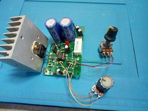
It’s an open circuit. The current limiting resistor is 0.33 ohm. With this value, I couldn’t get 3 amps at high voltages. I changed the resistor value with 0.22 ohms. It provided sufficient current. I used TIP35C for power transistor, 2SC5200 can be used instead. Use a large or fan heatsink for the output transistor.
Note: Since I do not have NE5532 opamp in my hand, I used TL082 opamp, which is not fully compatible, which may be the reason why it gives enough current. I recommend using NE5532.
30V 3A Adjustable Power Supply Circuit Diagram


I applied the 0.30V 0.3A Regulated power supply circuit as it is simpler than the similar ones and does not require additional adjustment, and the source is solid. In addition, a modified version of the same circuit was made. Instead of TL431, reference voltage is taken over the 78L05 regulator IC and information about the calculations of current and voltage settings is given.
I haven’t tried the 78L05 circuit, it will probably work… I added the PCB drawing to the file, anyone can try it.


Modified Power Supply Description
Maximum current setting: The maximum current can be adjusted from the resistors R8, R9 and the potentiometer P1 by the voltage divider according to the following.
formula np = [R9 / (P1 + R8)] + 1, (np = voltage ratio).
Sample:
R9 = 39k, P1 = 10k, R8 = 0.1k ….. np = [39 / (10 + 0.1)] + 1 ….. np = 4.86
Reference voltage from 78L05 = 5V.
5 / 4.86 = 1.028V = maximum voltage at comparator input (NE5532)
The sensing resistor has a value of 0.33Ω.
1.028 / 0.33 = 3.11A = maximum current.
Maximum Voltage setting: The maximum output voltage is set by resistors R15 and R16. The 5V reference voltage is connected via potentiometer P2 and resistor R10 to the opamp input, which is connected as a constant gain DC amplifier. The gain is set according to the formula a = 1 + (R16 / R15).
Sample:
R16 = 8k2, R15 = 1k5 ….. a = 1 + (8.2 / 1.5) ….. a = 6.46 (gain).
Reference voltage = 5V ….. 5 x 6.46 = 32.3V. This is the maximum output voltage.
PCB drawing of 0-30V 3A Regulated Power supply circuit prepared with Sprint layout 6 program PCB dimensions 79.3x48mm
Source: ok2cd.cz/reg.-zdroj-0—30v.html
Password: 320volt.com
Published: 2021/09/19 Tags: power electronic projects, power supply circuit, power supply project
Hi, I made the modified power supply circuit with the 78l05 regulator and the ne5532, so everything fine, but
the minimum current is 33mA !
Is there any way to reduce minimum current? Or is it normal?
Thank you a lot.
Hi,
The minimum should be 10ma. If you are using a current meter module for measurement, there may be a calibration problem. Measure with a digital multimeter. If the problem persists; Try the tl431 version (small modification)
Is it possible to increase current to 6A somehow connecting 2N3055 in paralel?
Hi, Add 0.22 ohm 5w resistor to the emitters of the 2n3055 transistors reduce the value of the current limiting resistor. Note connect a small heatsink to the bd139 transistor + I haven’t tried power up 🙂
is it posiable Master to slave Tracking for series and peralell supply ?
not possible
This power supply is not able to deliver 3A, use 1A by enlarging R14 to 1 Ohm and a larger heatsink. It is based upon https://www.americanradiohistory.com/UK/Practical-Electronics/70s/Practical-Electronics-1978-10.pdf https://www.smartkit.gr/stabilised-power-supply-0-30v-3a-m.html http://img.banggood.com/file/products/201505080459530-30Vinstall.pdf https://www.banggood.com/0-30V-2mA-3A-Adjustable-DC-Regulated-Power-Supply-DIY-Kit-p-958308.html that all face the same problem.
For 3A you need 2 power transistors in parallel, a larger heatsink, and larger electrolytics. For 30V out of a regular transformer you need an opamp that can withstand more than 40V, because you supply additional -3.9V.
Hi, thank you for feedback 👍
Good day,
I have a question about the construction of this rectifier. When I connect the 12V 25W bulb, the current protection is immediately activated. I can’t reach a voltage of at least 2v. It seems that with the given resistor values I cannot reach 10A current. And I think that the given calculation is not OK. Can someone help me with the calculations for the specified current of 10A. Thanks in advance.
J’ai réalisé cette alimentation et j’ai découvert qu’elle n’est protégée contre les courts-circuits francs ..avez vous vu et testé ce problème !!!? … mérci
I made this power supply and discovered that it is not protected against direct short circuits..have you seen and tested this problem!!!? … THANKS
Hello, I did a short circuit test and saw no problem.
This is more complicated but the defects and possible solutions are explained, sorry for the moment only in Italian, but it will be easy to translate 😉
DIGITAL LINEAR POWER SUPPLY: https://www.devincentiis.it/index.php?route=information/information&information_id=6