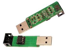
USB programmer There are few components – the ATtiny45 microcontroller, two Zener diodes, a capacitor and several resistors. Of course, there are still connectors – USB plug and IDC-6 plug. Resistor R1 informs host about presence of USB device transmitting data in Slow mode.
The resistors R2 and R3 in combination with D1 and D2 provide maximum voltages on the 3.6 V, not 5 V, because the +5 V voltage on the bus causes SYNC errors. R4 … R6 resistors protect the programmed circuit from damage if it is powered by a voltage lower than 5 V.
JP1 jumper should be open. It is assumed only when you want to power up the USB chip. Obviously, you need to keep in mind the limitations of the maximum permissible load current and the voltage range provided by the USB.
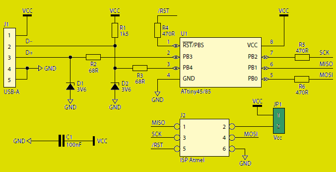
AVR USB programmer schematic diagram
The whole programmer can be placed in a heat-shrink sleeve, but beforehand the microcontroller must be programmed. Microcontrollers provided in AVT sets are already programmed, but if you are building your own programmer, you have to do it yourself.
The microcontroller should be programmed in high-voltage mode because the zero line works like typical I / O. Such programmers have so called. parallel. However, you can do otherwise. Most programs do not allow the RST line to be disabled in SPI mode, but for example, AvrDude offers this capability. Using the Burn-OMat overlay, you can switch the RST line to I / O mode, only to enable Expert mode.
Configuring AVR Studio to work with USB tiny AVR Programmer:
From the “Tools” menu, select “Customize …”.
In the newly opened “Command” window, select the “Tools” tab.
We point to the “New” icon or press the “Insert” key.
We enter the name of the programmer, eg “USBtiny”.
In the “Command” window we indicate the path to “avrdude” (eg: C: WinAVR-20100110binavrdude.exe).
In the arguments window we specify the parameters: “-p m168 -c usbtinyp -P usb -U flash: w:” file. hex: a -U flash: v: “.hex file: a”, where “m168” is the type of processor.
In the “Initial directory”, enter the path to the file (note the final character “”)
We approve the changes with the “Close” button.
In order to program the microcontroller select the name of our programmer in the “Tools” menu (in this example it is “USBtiny”).
Configuring Bascom to work with USB tiny AVR Programmer:
From the menu select “Options / Programmer”.
Select “External programmer” from the drop-down list.
In the “Other” tab (at the bottom of the window) we give the path to “avrdude”.
In the parameter window, type “avrdude” -p m168 -c usbtiny -U flash: w: “{FILE}”: a -U flash: Where “m168” is the type of processor.
Programming with the F4 key or the “Program chip” icon.
Supported microcontrollers and their codes
|
ATmega128 |
m128 |
|
ATmega1280 |
m1280 |
|
ATmega1281 |
m1281 |
|
ATmega16 |
m16 |
|
ATmega162 |
m162 |
|
ATmega164 |
m164 |
|
ATmega168 |
m168 |
|
ATmega169 |
m169 |
|
ATmega2560 |
m2560 |
|
ATmega2561 |
m2561 |
|
ATmega32 |
m32 |
|
ATmega324 |
m324 |
|
ATmega328 |
m328 |
|
ATmega329 |
m329 |
|
ATmega3290 |
m3290 |
|
ATmega48 |
m48 |
|
ATmega64 |
m64 |
|
ATmega640 |
m640 |
|
ATmega644 |
m644 |
|
ATmega649 |
m649 |
|
ATmega6490 |
m6490 |
|
ATmega8 |
m8 |
|
ATmega8515 |
m8515 |
|
ATmega8535 |
m8535 |
|
ATmega88 |
m88 |
|
ATtiny12 |
t12 |
|
ATtiny13 |
t13 |
|
ATtiny15 |
t15 |
|
ATtiny2313 |
t2313 |
|
ATtiny25 |
t25 |
|
ATtiny26 |
t26 |
|
ATtiny45 |
t45 |
|
ATtiny85 |
t85 |
![]()
FILE DOWNLOAD LINK LIST (in TXT format): LINKS-25822.zip


Kleiner USB-Programmierer AVR Mikrocontroller AVRDUDE
USB-Programmierer Es gibt wenige Komponenten – den ATtiny45-Mikrocontroller, zwei Zener-Dioden, einen Kondensator und mehrere Widerstände. Natürlich gibt es noch Anschlüsse – USB-Stecker und IDC-6-Stecker. Der Widerstand R1 informiert den Host über das Vorhandensein des USB-Geräts, das Daten im langsamen Modus überträgt.
Die Widerstände R2 und R3 in Kombination mit D1 und D2 liefern maximale Spannungen an den 3,6 V, nicht an 5 V, da die Spannung von +5 V am Bus SYNC-Fehler verursacht. Die Widerstände R4 … R6 schützen die programmierte Schaltung vor Beschädigung, wenn sie mit einer Spannung unter 5 V versorgt wird.
JP1 Jumper sollte offen sein. Es wird nur angenommen, wenn Sie den USB-Chip einschalten wollen. Natürlich müssen Sie die Beschränkungen des maximal zulässigen Laststroms und des vom USB bereitgestellten Spannungsbereichs beachten.
AVR USB-Programmierschema