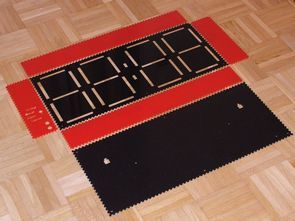
In fact, what lies At the forefront of the digital but mechanics should have been a wonderful project:) is an interesting time in the atmega8 microcontroller time and when the mind comes to the display, lcd, led, but the author is using a different method to display the time information. Figures are the red and…
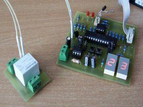
Thermostat circuit for 2 pt100 temperature measurement used atmega8 mikrüdenetleyici sensor pt100 sensors gives the circuit output is being used according to the information received. The thermostat is located on the circuit board led display temperature value. Connect the relay outputs can be controlled by a variety of devices, TRIAC, etc. PT100 sensor, Thermostat for…
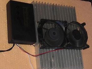
Peltier Thermoelectric Cooler Is how it works with 12-Volt Feed information and 50W Peltier Mini Fridge built on the lcd display after the ATmega8 microcontroller from a more advanced peltier control circuit. The value can be determined, the refrigeration circuit can be adjusted to the heat to start the PWM information, 2 × 16 lcd…
Power supply circuit consists of a few sections 04 to 0 30v power supply based on solid TL081 op amp circuit 2N3055 power transistor quite popular and a classic by many people applied. LCD display on the floor (AVT2857) the ATmega8 microcontroller used voltage, current imaging as well as the DS18B20 sensor heat thanks değerinide…
Built on the atmega 8 microcontroller Logic Analyzer circuit for nokia 5110 display lcd display kullanılanılıyor crafted with AVRstudio Software four. source software insurance settings schema, pcb, etc. files. Frequency capture 400 kHz, Max input voltage 5v dc, operating voltage 5v (4 x 1.2 v rechargeable battery) to capture high speed signals, signal 3.7 ms,…
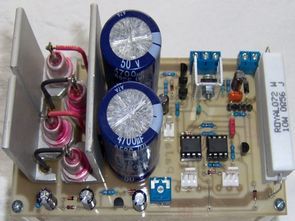
Elektor the number given in the magazine’s old modified version of the adjustable power supply circuit .. 0 0 5 between 30v voltage and current settings can be made. Control solid TL082 op amp used in the output stage has the power transistor 2N3772 60 volts 30 amps. In addition, the circuit’s voltage and amperage…
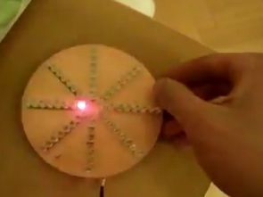
Led effect circuit 64 leds LEDs on the printed circuit board disposed in the impeller has a very different effect. A plurality of circuit components used SMD type. Effects displacement, velocity pcb solder buttons mounted face. Source code for the project and provided drawings eagle pcb diagram. Source: paja-trb.unas.cz/elektronika/konstrukce/snowflake.html FILE DOWNLOAD LINK LIST (in TXT…
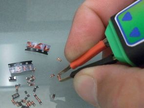
Interestingly circuited actually zener diode test measuring instruments should have a property zener measurement of when you are secure, a voltage see better, but so far no measuring instruments equipped with this feature I have not seen though the circuit design a separate beauty measurement probe to be in shape to use is easy. Zener…
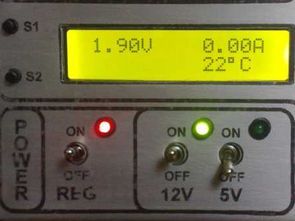
Very high quality design of the digital power supply circuit. Voltage current of 2 × 16 lcd display of the beauty and power of the switching mode operation switching DCDC Madden LM2576 ADJ (adj = adjustable) used the output voltage 0 …30 volt current is 0.3 amps between the hex file of the source code…
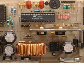
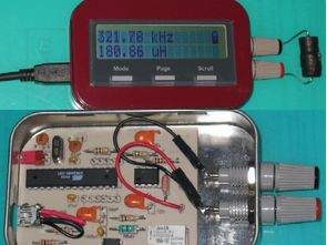
Coil measurement “Inductance Meter” circuit based on Atmega8 microcontroller LCD HD44780 driver and the system’s power supply is taken from the USB port on the computer or adapter operated with the circuit. Circuit of the box mints box cut and processed interesting metal, enamel paint made circuit optimized 🙂 The LCD screen of the circuit…