DRV8402 Motor Driver Circuit The main component is the microcontroller dsPIC30F2010, who for its activities needs outside of the power supply voltage also a source of accurate clock pulses. In order to achieve the speed of 30 MIPs, we had to calculate the speed of the desired crystal. Each instruction takes four bars of the hourly pulse and when using the multipliers impulses 16x PLL we get a crystal about the size of 7,3728 MHz. According to the datasheet of the processor is needed to connect to the input of the crystal two capacitors.
dsPIC30F2010 Motor Control Circuit Schematic

DRV8402 is a very powerful double full H-bridge with integrated MOSFET transistors. Their internal resistance RDS(on) has a low value of 80 m at a temperature of 25 °C…. Each of the jumper is composed of two puls each separate country. It can be every half of the power the different levels of the supply voltage. And when the power supply voltage to 50V. Current the load of each bridge is 5 And continuous at peak times up to 12 a And at parallel involvement of both bridges can be controlled the flow 10 And in the peak loads in 24 And. This circuit allows the management of conventional and brushless dc motors and control 3-phase synchronous motors with permanent magnets. For the management of the engines are on circuit inputs a PWM signal, which may be in the range from 25 KHz to 500 KHz at high efficiency and good control.
DRV8402 Schematic Dual Full Bridge PWM Motor Driver

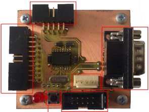
For a hardware implementation of the procedure we designed two modules. The first module is folded from the microcontroller DSPIC30F2010 and auxiliary circuits required to obtain the desired position and the resulting control PWM signal. Further has serial communications for connection to a PC and own a source of reference voltage for accurate measurement of quantities from the a/D converter.

![]() pwm motor dirver circuit pcb schematic all files alternative links:
pwm motor dirver circuit pcb schematic all files alternative links:
FILE DOWNLOAD LINK LIST (in TXT format): LINKS-25690.zip
Published: 2016/06/18 Tags: dspic projects, microchip projects, microcontroller projects, motor control circuit, motor driver circuit, pwm circuits
4X60W Car Amplifier Circuit LM3886 SG3525 DC DC Converter
Amplifier 4×60 Watts. To its solution was first selected integrated circuit LM3886T. The proposal continued the calculations and the election of the additional components of the integrated circuit and the design of printed circuit connections. To the end amplifier was also designed system of active cooling. In the fourth chapter was made the proposal of the converter voltage. It was first designed portion control circuit on a separate printed circuit board with adjustable frequency and duty cycle of switching pulses.
dsPIC30F2010 Motor Treiber Schaltung DRV8402
DRV8402 Motor-Treiber-Schaltung Die wichtigste Komponente ist der mikrocontroller dsPIC30F2010, wer für seine Aktivitäten benötigt, die außerhalb der Versorgungsspannung auch eine Quelle der genaue Taktsignale. Um die Geschwindigkeit von 30 MIPs, mussten wir die Geschwindigkeit berechnen der gewünschten Kristalle. Jeder Unterricht dauert vier bars stündlich Puls und bei der Verwendung der Multiplikatoren Impulse 16x PLL, erhalten wir einen Kristall in etwa die Größe von 7,3728 MHz. Laut Datenblatt des Prozessors benötigt wird, um eine Verbindung zu dem Eingang des crystal zwei kondensatoren.