Power LED driver circuit based on Atmel ATmega8 is working with 12 volt 3 1 watt Luxeon power LEDs with PWM buck converter is operated ATmega-8 a good example source code to solve logic diagram drawing have PCBs.
Power LED Driver PWM

LUTW stands for Light Up The World which is an organisation which aims to assist poor and remote villages in developing countries obtain a reliable and affordable White Light Emitting Diode (WLED) based form of lighting.
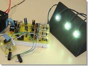
The WLEDs being used in this project are a revolutionary, energy efficient and ultra compact new light source, combing the lifetime and reliabilty advantages of Light Emitting Diodes (LED)with the brightness of conventional lighting. These WLEDs require more power than conventional LEDs and to ensure optimum light output, they must be driven at a constant current.
Due to variations of the forward voltage drop across these WLEDs, a smart driving circuit is required to drive up to three of these WLEDs at their optimum power levels whilst also protecting them against voltage and current surges.
The driver that has been developed is a micro-controller based circuit that operates using the buck converter topology. The current in each WLED is constantly sensed by the micro-controller which then adjusts it’s PWM output into the power electronics stage which then drives the WLED.
Overview Power LED driver Document
The following report documents the procedures and methods used to design and implement an LED driver module. A chapter-by-chapter overview is detailed below.
Chapter 2 of this document contains background information on the Luxeon LED’s along with detailing relevant converter theory, which is crucial in further understanding of the design sections. An overview of currently available devices is also contained in the section.
Chapter 3 derives the specifications of the driver to be developed. It achieves this by breaking down the driver into subsystems; with the specifications, both hardware and software, of the final driver derived from the individual requirements of each subsystem.
Chapter 4 details how the project was originally planned, with goals and milestones being developed. It also details how these original plans changed and how new milestones were set and achieved.
Chapter 5 details the hardware implementation of the driver. It starts by describing the requirements of the hardware and how the hardware was selected for the system noting possible component alternatives. Furthermore, this chapter comments on the key hardware implementation decisions made.
Chapter 6 contains the software implementation of the driver, outlining the requirements of the software and how it is used to control the hardware of the driver.
Chapter 7 details how the final implantation of the hardware and software meets the design specifications of Chapter 3. The result of testing the final product and the functionality of it is compared with the original specifications. The author’s performance in completing this thesis is also reviewed, with the strengths and weaknesses of the author evaluated, along with which additional skills were gained in order to complete the project.
Chapter 8 gives an outline on how this project could possibly be improved, and suggests additions and optimizations that could be implemented into the current design as well as into any future versions of this device.
Chapter 9 provides a brief overview of the entire project, outlining the goals of the project, what was actually achieved and how well it performed. This chapter also summarises conclusions which were made previously in this report.
source: innovexpo.itee.uq.edu.au/2003/exhibits/s362988/ Power LED Driver Circuit LED Current Sources Atmega8 PWM alternative link:
Password: 320volt.com
Published: 2009/12/26 Tags: atmega8 projects, avr project, led projects, microcontroller projects, pwm circuits
100Watt PV Panel Converter Atmega8 100W DC to AC ICL7667 ETD34
The use of solar energy will be the topic for a long time an active electronic circuit is used a lot in this business at one of these inverter dc to ac converters. Ac dc voltage from PV module circuit (240Vac) is turning 100 watts of power system voltage control provided by Atmel ATmega8. ATmega to drive MOSFETs in the output ICL7667 (Dual-Power MOSFET Driver) The transformer used etd34
All details about the circuit formula’s calculations also pcb circuit diagrams and drawings given ATMega8 software.
Most excellent of all the floors of the circuit given in separate schemas (PV current, voltage sensing, drivers, etc..) You can use this circuit for different applications or projects can be useful in the calculations.
100W Solar Panel Inverter