HI-FI 2 x 80W Power Amplifier on STK442-090 Micro assembly Most radio amateurs can be divided into two categories: supporters and opponents of microcircuit amplifiers. As arguments for using such amplifiers, the former cite the simplicity of the circuit, high reliability and stability of operation due to the high integration of the microcircuit. As a rule, the number of transistors in the micro circuit is several, or even tens of times, greater than their number in a conventional amplifier “on bulk”.
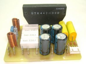
In a simple way, you can say this: if you disassemble the microassembly, then its component elements will be clearly visible: transistors, SMD resistors, and so on.
Japanese engineers from SANYO (now a subsidiary of Panasonic) have developed the STK GIS series. Microassemblies immediately gained a reputation for high fidelity amplifiers. Technics has expressed its confidence in the quality of these GISs in its legendary amplifiers.
SANYO micro-assemblies in retail are quite expensive and there is a chance to run into a fake. Therefore, you must buy from serious, trusted suppliers who will not risk their reputation.
I will not engage in advertising, as well as write how to distinguish between the original and the fake. There are specialized forums for this – use the search. And we will focus on technical issues.
STK442-090 Amplifier Schematic Diagram

STK442-090 SPECIFICATION
STK442-090 is a dual-channel UMZCH operating in gain mode AB. Decorated in a 14-pin package.
Table of maximum values. Ta = 25 deg
Let me make some comments on this scheme.
1. Filter capacitors in the power supply circuit (on the 100uF / 100V circuit) are best supplied with a larger capacity from the LowESR series. We use 1000uF / 50V.
2. Resistors marked (* 1): 5-watt SQP, nominal 0.22 Ohm – 0.33 Ohm.
3. The capacitors in the feedback (on the 100uF / 10V circuit) should also be LowESR series and the highest quality. It would be nice to additionally shunt them with a 0.1uF film capacitor. This should improve the sound at high frequencies.
4. We strongly do not recommend the use of electrolytic isolation capacitors (on the 2.2uF / 50V circuit). Film behave much better. We use a metal film polyethylene terephthalate CL20 (analogue K73-11), with a capacity of 2.2uF.
5. The output choke (in the 3uH circuit) is wound on a 2-watt 4.7 Ohm resistor (which in the 4.7ohm circuit) in a row with a wire of at least D = 0.8 mm.
6. The manufacturer provides power supply data for a 6 Ohm load only. We fill this gap:
The board is designed for the installation of power contacts DJ610-6.3 (TA-M). The signal part uses the H-04 pitch 2.54mm connector, but you can take the PLS-xx with the appropriate pitch. The output choke is frameless, wound with a wire of diameter 1.0 mm on a 6 mm frame and has 15 turns. In this case, a 4.7 ohm resistor, which should be connected in parallel with the inductor, is absent on the board.
The appearance of the assembled board can be found in the linked link at the beginning of the article. Good luck to everyone and creative mood!


Source: mariolla.com/index.php/amplifier/34-stk442-090.html
Password: 320volt.com
Published: 2019/08/08 Tags: audio amplifier circuits, ic amplifier
Circuit d’amplification STK442-090
Le circuit amplificateur STK442-090 proposé est un compromis, car le STK442-090 est un micro-assemblage, c’est aussi un circuit intégré hybride (SIG). Ce que c’est? Prenez un extrait de Wikipédia: “le micro-assemblage est un circuit intégré dans lequel, avec des éléments inextricablement connectés à la surface ou dans le volume du substrat, des éléments micro-miniatures montés (transistors, diodes semi-conductrices, inductances, appareils électroniques à vide, des résonateurs à quartz, etc.) sont utilisés ».
D’une manière simple, vous pouvez dire ceci: si vous démontez le micro-assemblage, ses éléments constitutifs seront clairement visibles: transistors, résistances SMD, etc.
Les ingénieurs japonais de SANYO (maintenant une filiale de Panasonic) ont développé la série STK GIS. Les micro-assemblages ont immédiatement acquis une réputation d’amplificateurs haute fidélité. Technics a exprimé sa confiance dans la qualité de ces SIG dans ses amplificateurs légendaires.
Why the copper path in PCB watermarked?
Could you please send me the version of not watermarked path..
Hi, The file has been updated (pdf pcb drawing added). Download it again.