
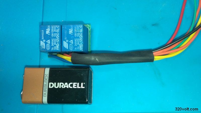
The melody horn circuit is based on the PIC16F1827 microcontroller. The circuit can be connected to 2 horns with double relays. Relay is used for horn control. Relays 12V 10A power snail horn or similar can be used. There are 3 melodies, the first is John carpenter the end, the others are rhythmic. If it is 4, the fixed horn mode activates this flat horn without melody. In addition, pressing and holding the melody change button for 2 seconds automatically switches to this mode.
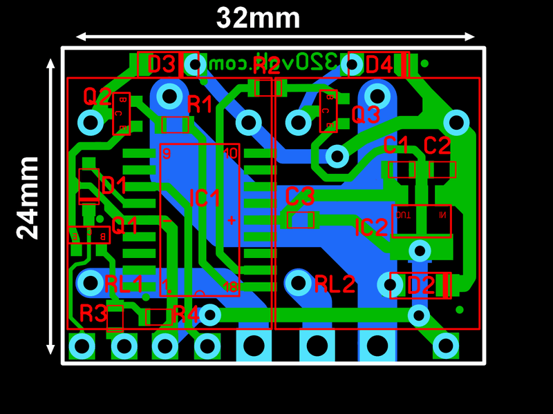
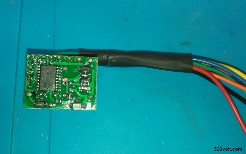
The PCB design of the melody horn circuit was made with Sprint layout 6, the drawing is double-decker, all components are mounted under the board, except for the relays. PCB dimensions 3.2cm 2.4cm operating voltage 12V (relays can work with 24V, I haven’t tried it)
There are three melodies in the melody horn circuit. 1 John Carpenter The End the other two are rhythmic.
Melody Horn Circuit Diagram
pcb, hex files of melody horn circuit: 28322a.zip pass: 320volt.com


i need this source code. please give me ..