The electronic control circuit for the 4-cylinder internal combustion engine is designed for 4-cylinder internal combustion engines to work with both the external switch, the ignition unit and the ignition coils using the built-in high voltage switches. There is a universal “DH” input for connecting a Hall sensor or a breaker contact. The U2 LM555 IC is used, which normalizes the input pulses according to time and reduces the possibility of false alarms caused by noise and other noises in the input signal.
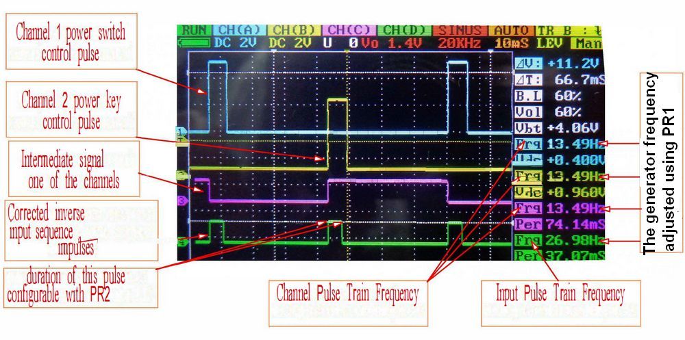
At its output, pulses in TTL format with a certain duration are formed (the parameter is set using the potentiometer PR2). To work with the inductive sensor “IND”, the input is made in the transistor Q1, which is also processed by the signal from the collector U2. U2 operation indication is made on the HL4 LED. Pulses generated by U2 go to the count input of trigger U6.2.
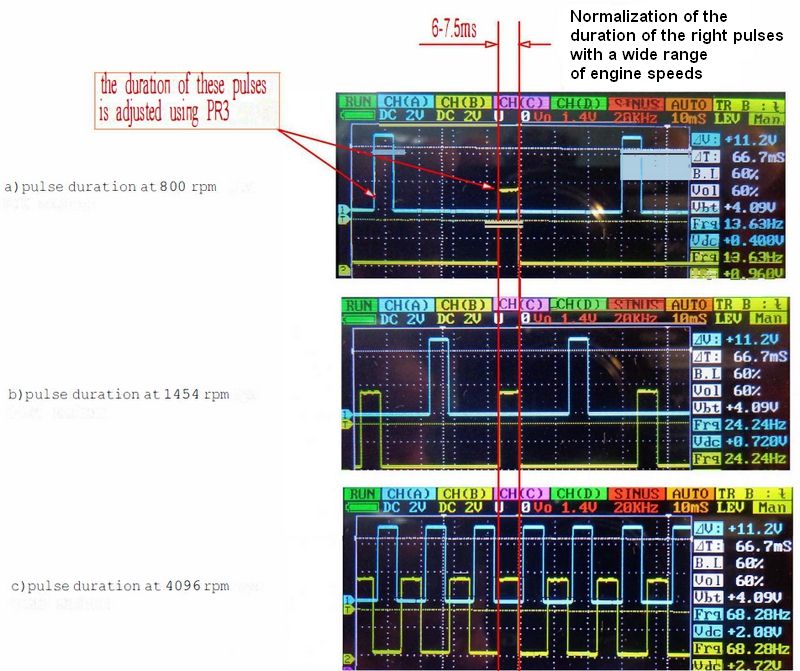
With a frequency reduced by half, the pulses (roundabout) reach the inlets of the reshapes (U4, U5), whereby the pulses of a certain duration are formed and ensure the stability of the internal combustion engine. From the outputs of the shapers (U4, U5), the pulses are connected directly to the inputs of the drivers (TC4420 U7, U8), which control the MOSFET-IGBT transistors and, in turn, switch the primary windings of the ignition. HL6, HL7 LEDs are driver operation indicator. The same drivers can work successfully with bipolar high-power transistors of various types (single or composite). In addition, the signal from the outputs of the shapers (U4, U5) also controls transistors Q12, Q13, which simulate the operation of breaker contacts for interaction with external switches or ignition units. The duration of the pulses at the outputs of the shapers is adjusted using the potentiometer PR3.
Electronic distributor scheme for a 4-cylinder internal combustion engine
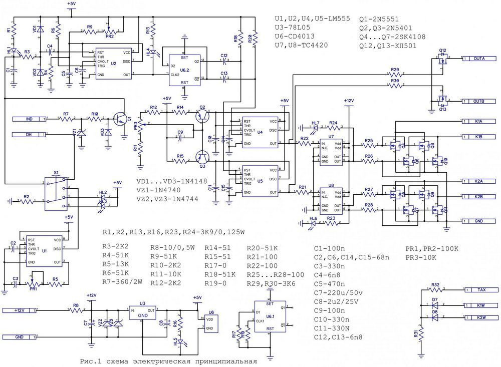
The device, in addition to the nodes described above, includes a generator that simulates the operation of sensors and can replace them in some emergency. The frequency of the generator ranges from 20 to 200 Hz, which corresponds to 600-6000 rpm of a 4-cylinder internal combustion engine. With the help of this generator, the device is also configured as a whole. The generator is connected to the device instead of the “DH” input using the S1 switch. Switch positions are indicated by HL2 (DH input connected) and HL3 (generator connected) LEDs.
The control circuit of the device is supplied with a voltage of + 5V from the stabilizer U3, the transistor drivers are powered directly from the on-board network of the car through a protective resistor R8. The device is protected from polarity change and overvoltage by installing zener diodes VZ2, VZ3 in parallel with the input voltage in the conventional connection (via R8). +5V power is indicated by the HL5 LED.
Electronic Dispenser Features:
Supply voltage 9-19V (without protective components VZ2, VZ3)
The current consumed by the EMC in the range of no-load supply voltages is not more than 40mA
Frequency of built-in pulse generator 20-200Hz
Duration of output pulses (duration of short-circuit current) not less than 5.5 ms, not more than 7 ms at motor speeds of 800-6000 rpm
Allowable load current for each switch up to 20A (using specified transistors)
DH input control signals – TTL (0…+5V) or short-circuit sequence with a common wire;
Input control signal IND – sinusoidal alternating voltage up to 30V
Signals at outputs OUT A, OUT B, – channel switching frequency of the input of the controlled device (switch) (imitation of the operation of the breaker contact) upstream short-circuit sequence to a common wire up to 200 mA
The work of -2K is carried out as follows:
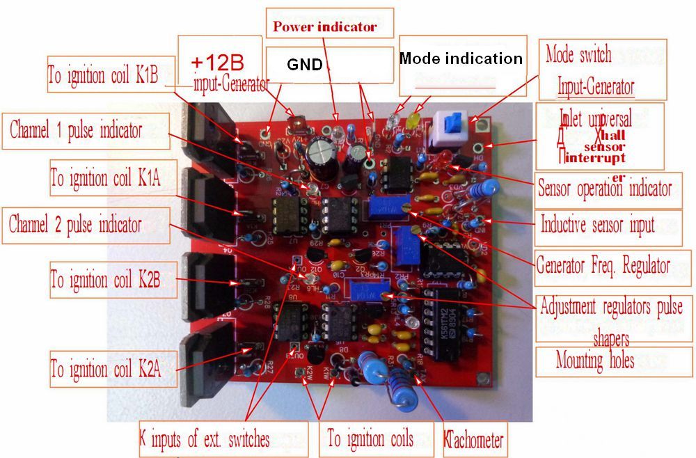
The HL5 power indicator LED lights up on the board when the supply voltage is applied to the corresponding terminals. Simultaneously, one of the HL4 (pulse shaper indicator) and HL2 / HL3 indicators lights up depending on the state (pressed) of the on-off switch S1 “generator input”. If the generator mode is enabled, the HL6, HL7 indicators will flicker at the channel change frequency. In “input” mode, these indicators go out until a series of signals is sent to the EMU input (ie in ignition off mode).
While the motor is running, these indicators will also flicker at the channel switching frequency (equal to 1/2 the input signal frequency). For this, the corresponding EMC input must be connected to the crankshaft speed sensor (Hall sensor, contact breaker, inductive sensor). Incoming pulses to any of the EMU inputs are processed by the input circuit. Calculation of the duration of the output pulses is necessary to reduce the excessive duration of the current flow through the primary winding of the 1st ignition coil (SC) and the power switch, which eliminates overheating of these components when operating at low speeds.
Each of the EMU channels has a high load capacity driver capable of driving a pair of powerful power switches. As a switch, it is possible to use powerful MOSFET-, IGBT- transistors or composite transistors of bipolar n-p-n structure (Darlington). Transistor parameters should not be less than 15A (current) and 350V (voltage).
For Darlington transistors, the current gain should be at least 400. Transistors used as switches when testing the EMU-2K: IRF460, 2SK4108 (MOSFET), RHJ3047, GT30J124 (IGBT), BU931ZP (Darlington), KT834A. No special differences were noticed during the operation of the device using these transistors, but in actual operation this difference can be noticed.
In the EMU-2K, the passage of current through any short-circuit in the absence of input pulses (with the ignition off) is excluded, which eliminates the heating of the short-circuit with the ignition off and from the power take-off.
For safe operation:
1. The EMU board must be placed in a sealed, moisture-proof enclosure (case) with a minimum heat sink surface area of 200 cm2.
2. On the mounting side of the EMU board, there should be no electrical connections other than the case surface and the common cable (GND).
3. The housings of the output transistors should be fixed to the inner surface of the housing with special heat-conducting (silicone or mica) gaskets.
4. Although the EMC circuit is protected against power voltage reversal, reversing the polarity will damage the circuit.
5. Short-circuiting/disconnecting the EMU / EMU during operation will damage the circuit.
6. Adjustment of pulse shapers is not possible without experience and oscilloscope
7. Touching components on the EMU board during operation will damage the circuit.
8. Removing components plugged into sockets during operation will damage the circuit.
9. Removing components plugged into sockets without antistatic protection (if a socket is present) will damage the circuit.
Before using the EMU-2K, you should make sure that it works according to the waveforms and LED indicator provided. If the pulses differ significantly from those shown on the oscillograms or are absent, it is necessary to find out the cause of the violation of the operating modes (incident or insufficient supply voltage, absence of input pulses or generator pulses, malfunction of external components). )
Source: cxem.net/avto/electronics/4-178.php
Alternative List of download files (in TXT format) for Electronic Distributor circuit for Internal Combustion Engine 28409a.zip pass: 320volt.com