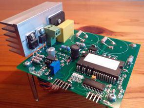
The inverter is fed from a single phase with 230V alternating voltage with a power of about 400W. The output gives a 3-phase voltage of 3x230V. Inverter diagram, dsPIC33FJ32MC102 software, Kicad PCB design are attached.
Main control IC FNA41560. There is a PFC power factor correction circuit at the inverter input, which ensures that the current drawn from the network does not deteriorate and is in the same phase with the voltage.
The voltage across the filter capacitors is about 430V at no load and drops to 400V under load. In the inverter, the transistors are switched at a frequency of 5 kHz, because the FNA41560 IC is optimized for this frequency, the duration of the transistors is about 1.2 μs
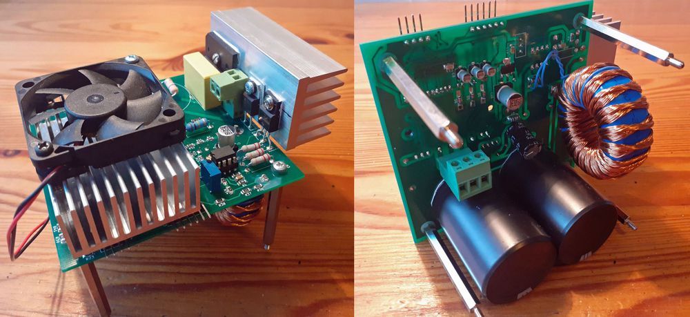
The inverter is protected against high temperature (above 105C), short circuit (5A), high voltage (460V) across the filter capacitors. The short circuit protection automatically resets (acts as current limiting) at the end of each PWM cycle. This can be modified to be kept in the PIC33FJ32MC102 P1FLTACON microcontroller register.
In this mode, PWM is turned off and stopped until the problem is fixed. The frequency is regulated by a multi-turn potentiometer with a resolution of 0.1 Hz. Adjustable frequency range from 1Hz to 80Hz. Usable range starts at 5Hz. A VSM-spatial vector modulation algorithm is used to generate the output signal, allowing you to make the most of the DC voltage supplied to the FNA41560 module.
The differences in waveforms created with SPWM and SVM are as follows.
In case of SPWM, the maximum phase-to-phase voltage at the output of the inverter cannot be more than v3 / 2 x Udc, for SVM it is equal to Udc
The SVM method gives about 15% higher output voltage compared to the sinusoidal PWM method.
It should be noted that the power supply of the circuit is not isolated from the mains and special precautions must be taken during use. The absence of galvanic isolation is potentially dangerous.
Files of 230V 3 Phase Inverter project with PFC: 28132a.rar pass: 320volt.com


