Leach amplifier design is very high quality and has many applications. PCB design is very good in these projects. Source eagle CAD files material list measurement values are given. The author gave detailed explanations about transistor selection, problems encountered, solutions and other issues. I am adding the translation without editing.
Amplifier LVA100
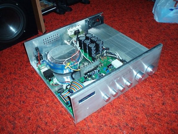
I have been looking for a quality audio amplifier with 100W power for a long time. My recommendation was Leach or DPA220 amplifiers. I eventually scrapped the DPA220 to replace it with relatively old components, mainly because I didn’t have a DPS design. I’ve already built three pieces of Leach amplifiers modified by me, so I wanted to try something new off the top of my head.
I chose the following as priorities:
High quality terminal, excitation and oscillation transistors
Easily available and also relatively inexpensive parts
Sine wave power around 100W/4-OHM
High bandwidth
Completely symmetrical arrangement
In the differential stage I used the well-known low-noise BC550/BC560 transistors. These are preceded by a voltage source from BC546/BC556 transistors. For the differential stage I used a current source from a transistor with a red LED diode at its base. A current source solved in this way has higher temperature stability than a current source with a zener diode and also has less noise.
Another important part is the swing phase. The requirements for a quality transistor with a high voltage Uce, a large cutoff frequency and as flat a gain characteristic as possible, as well as a small junction capacitance are the following. Generally speaking, transistors designed for vertical video amplifiers are best suited here.
While looking at the datasheets I found some very good transistors. These were complementary transistors from the 2SA/2SC series. Unfortunately, I was surprised by the small availability of these transistors in our e-shops. Often they were not there at all, or only polarity had an effect. So I decided to find another one. In the end I chose the older KF469/KF470 types or equivalents. Perhaps they differed from 2SA/2SC only by a smaller cutoff frequency of around 70 MHz. I used the same transistors for the pre-exciter.
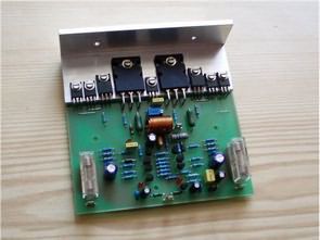
This is already followed by a driver consisting of transistors 2SA1837 and 2SC4793. They are quality transistors in a plastic case (insulating pads removed) at a very good price. Manufacturer Toshiba. I used 2SA1943/2SC5200 as the terminal transistor, these are Toshiba’s Japanese transistors. Designed for nf amplifiers with power up to 100W.
They have a relatively high cut-off frequency of 30MHz, a high voltage Uce of 230V and a collector current of 15A. MJL3281/MJL1302 transistors, which are also of high quality with similar parameters, were also taken into account. I decided on the first name practically only because of the convenient purchase. I haven’t tested it but I think it is possible to install MJL without any problems.
Resuscitation occurred without complications. I used a 2x45V/400W power supply with 15000uF filtering per branch. I turned the trimmer to adjust the quiescent current to the largest resistance value, i.e. the shaft as far to the right as possible!! I connected a resistor of approximately 82R to the positive arm via the ammeter. And when we turned on the source, the ammeter showed 30mA. By carefully turning the trimmer, we increased the quiescent current value to 50mA. The output voltage was around 13mV which was negligible, I did not match the components.
The next step was to measure the amplitude characteristic. I set 1kHz on the generator and the amplitude so that the amplifier is excited immediately after limiting. And I was increasing the frequency upwards. I noticed a -3dB drop around 180kHz. The lower cutoff frequency is below 20Hz. A rather wide frequency response is not due to the transmission of supersonic frequencies, but to a flatter phase response and therefore a smaller phase shift at 20 kHz.
At the output of the amplifier there is a choke and a Boucherot RC element, as well as protection diodes on the end transistors. If the amplifier will be used to drive the speaker in the subwoofer, it is possible to replace the output coil and its resistor with a wire bridge with a diameter of 1.5 mm, which will increase the damping factor. I would just like to point out that the amplifier does not include surge protection.
I decided this way for a smaller printed circuit board and also because in case the module is used to drive a woofer in a subwoofer or as a home amplifier, you plug it in once and it stays plugged in several times. Protection available for months or even years is unnecessary.
When I connected the amplifier to voltage, I did not hear any popping sound in the speaker, nor when I turned it off, only a soft attenuation of the “playback” sound. This pleasantly surprised me.
As the power supply, use a supply with a voltage of +/-45V (after filtering) to achieve 100W/4R power.
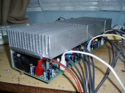
Heat transfer to the cooler is solved using the aluminum L profile. It is necessary to place an insulating pad under transistors T1, T2 and T7, mica coated with a thin layer of silicone vaseline will work well.
RMS power: 100W/4-OHM at +/-45V
Bandwidth: 10Hz – 180kHz /-3dB
Damping factor: >100
THD+n, IMD distortion: ? I’m sorry but I don’t have anything to measure harmonic distortion.
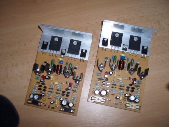
I installed two of these modules, they worked without problems at first connection.
Sound: Very “warm” sound without damaging the deep tones, sound that is not tiring even when listening to music for a long time. More pronounced treble.
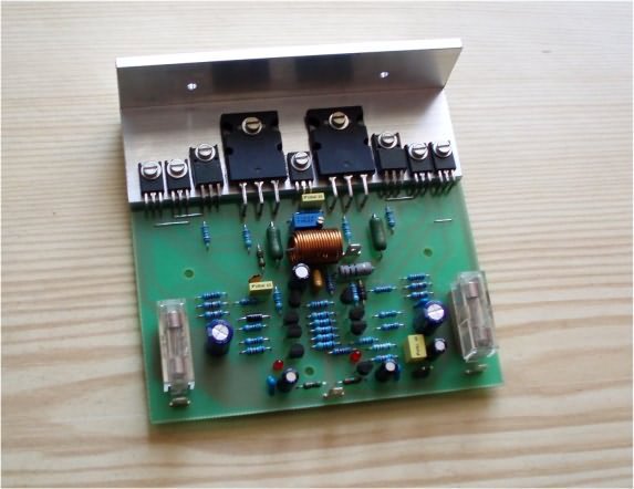
Amplifier LVA101
Lately I’ve started to enjoy designing power amplifiers. Things can always be improved, and it’s the same with power amplifiers. I tried to improve the amplifier I present here a little more than the previous LVA100. In the first prototype, other types of transistors were installed in both the oscillator and the driver. Equipped this way, it worked very well without needing to overcompensate.
The bandwidth was around 1 MHz, with bandwidth compensation reduced to roughly 700 kHz for better propagation of the rectangular signal. Unfortunately, due to the unavailability of these transistors, I had to use better available ones. After replacing these transistors, the amplifier with the original equipment began to oscillate intensively, the end transistors resisted the increased consumption, and only the fuses did not survive.
I reduced the gain of the differential amplifier by about 3 times, the compensations were kept original. With such a setup the bandwidth was around 900 kHz, but small overshoots appeared at the leading edges in the rectangular waveform, so I increased the compensation so that the bandwidth dropped to 650 kHz (measured without the output choke). With throttling, the bandwidth dropped to 400kHz at the 4R load resistor. I think this much bandwidth is unnecessary, but lately it is a trend and there is a lot of discussion about it. One of its advantages is that the phase shift at high frequencies is minimal, plus it is easier to limit the bandwidth than to increase it.
We are now closer to the description of the link. The amplifier has a conventional concept, I am a supporter of symmetrical arrangement. At the input there is a transistor differential amplifier, in the emitters of the transistors there are resistors to reduce the gain of this stage, in this case the entire amplifier becomes more stable. This stage is supported by current sources with transistors and red LEDs. Next comes the emitter follower.
It linearizes the entire connection because it amplifies the output of the differential amplifier with current so it is not loaded too much by the oscillating transistor. For the oscillation stage I used Sanya’s well-known high-quality video transistors 2SA1540 / 2SC3955. They have a cutoff frequency of 300 MHz, a capacitance of only 1.5pF and a fairly linear dependence of the gains on the current.
Compensation is applied from the output of the oscillating stage to the input of the emitter follower connected to the anti-saturation diode, but saturation suppression is only moderate. Next comes the prestimulus, from whose output the second feedback is executed, which performs the compensation function. There are already terminal transistors behind the driver. The well-known Toshiba 2SA1943 / 2SC5200 is used.
They are transistors designed for audio amplifiers up to 100W. There is an RL element at the output of the amplifier to alleviate the capacitive load. If we use the amplifier to power the speaker without passive crossovers, we can replace this RL element with a powerful jumper, thereby increasing the damping factor. The amplifier has no overcurrent protection; It is designed for residential conditions where frequent use is not expected, that is, there is almost no risk of short circuit at the output. Additionally, overcurrent protection is not as simple as it seems at first glance; If set incorrectly, it may cause distortion in the output signal.
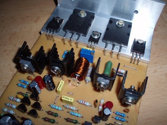
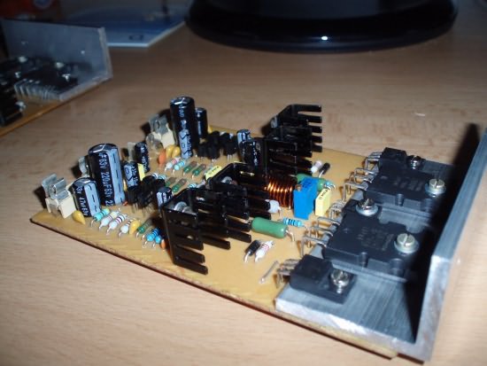
In addition to the differential amplifier and current sources, all transistors are placed on an aluminum L profile, which is then connected to the heatsink. I recommend applying silicone vaseline or other heat-conducting paste under the transistors and at the interface between the profile and the profile. cooler. The transistors at the end and the transistor used to detect the coolant temperature must be connected via a mica pad, the casing of the other transistors is plastic.
The amplifier should not be powered with a DC voltage higher than 2x42V. At such a voltage it provides just over 100W of power to a 4R load. Choose the classic quiescent current around 50mA through the terminal transistors.
I hope you find it useful when you first plug in the amplifier and that you are happy with the sound. I’m not saying it’s the top of the amps, but I think it’s at a pretty good level.
Features:
output power……………..100W / 4R
frequency bandwidth…… 10Hz – 400kHz / -3dB (up to 600kHz without output element)
damping factor………………………………..>100 at 4R
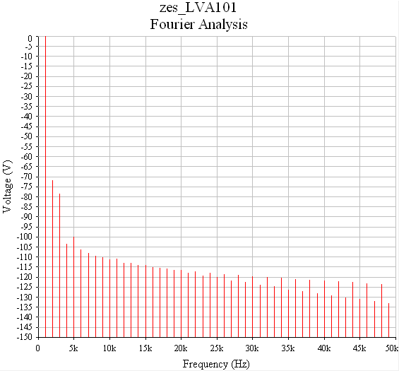
distortion………………0.028% / 1kHz (60W/4R)
0.008% / 1kHz (10W/4R)
0.080%/ 20kHz (60W/4R)
Sound: Very “warm” sound without damaging the deep tones, sound that is not tiring even when listening to music for a long time. More pronounced treble.
Added preview of simulated features. (measured at 80W/4R stimulation)
Leach LV version amplifier
This amplifier was created as a variant of the original Leach Amp v4.5. But Leach Amp v4.5 has a few flaws.
– end transistors are connected to the PCB with wires, which is not a good solution electrically. Parasitic inductance increases.
– temperature stabilization is carried out by four series-connected diodes located on the heatsink of the final transistors.
So I decided to edit it. The slowest part of the amplifier after this modification are the final transistors, which have a cutoff frequency of 30MHz compared to the original 2MHz. Therefore I strongly do not recommend connecting terminal transistors to DPS cables!
In this way, an amplifier equipped with fast transistors responds faster to deviations between input and output signals. Also, since such fast transistors usually have smaller input capacitances and therefore do not load the previous stage as much, this also reduces distortion at high frequencies, which is reflected in a higher speed. In my case there was no need to adjust the amplifier compensation. Relatively large resistors in the emitters of differential stage transistors reduce their gain, which contributes to better stability of the entire amplifier.
Amplifier parameters:
– harmonic and intermodulation distortion unfortunately I have nothing to measure, but it would be similar to the original concept of this amplifier (THD+N 0.02% 120W/1kHz; IMD 0.018% 60Hz/4kHz 4:1)
– At +/-42V supply voltage, I measured 120W/4R RMS power (approximately +/-55V supply voltage would be required for 200W/4R power)
– power bandwidth: 5Hz – 200kHz / -3dB 120W
– damping factor greater than 100 (unfortunately I do not have a sensitive enough measuring instrument)
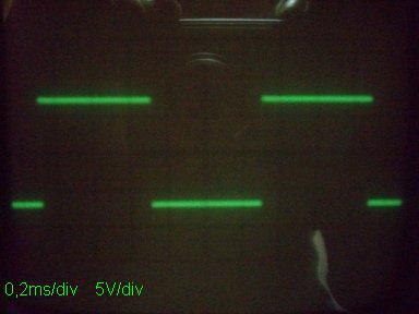
Rectangular waveform at output at 4R load
source: levex.wz.cz/levex.htm


