To reach the simple design of the power supply and at the same time easy output voltage and current limit, I decided to use the well-known monolithic integrated Adjustable voltage and current regulator L200 series in the case Pentawat with five outlets by ST Microelectronics. The voltage can be set to the values of two external resistors in range from 2.75 V to 36.0 V, provided that the input supply voltage is at least 2.5 V higher. Otherwise, the maximum input voltage that can withstand circuit is 60 V. Compared to other similar circuits, there is also still a possibility and simply set size of the output current. If this setting is not used, is current limited internally to approximately 2A (3,6 A), in an ideal cooling. Depending on the temperature Housing is possibly current or voltage output restricted to lower values, and to prevent damage to the circuit and its thermal and power overload. This circuit is very similar to a friend LM317T series stabilizer in the housing TO220, but unlike him, has brought out sensing input current limit (pin 2 – limitation), similarly as in the case UA723CN DIL14. The circuit is in the housing PENTAWAT.
L200 Power Supply Circuit Schematic

Stabilizer L200CV The following instructions and design is designed for those who want to build quality single power supply according to the above requirements. the source has continuously adjustable output voltage range of 0V to 30V, adjustable maximum output current of 10mA to 1,000 mA. The source can also be equipped with fine control output voltage (a pair of potentiometers – 10k coarse adjustment / fine adjustment 250Ω), and possibly a measuring device for measuring the output voltage and current.

The base source is a monolithic integrated stabilizer L200CV with which it is can be achieved in a basic diagram of the output voltage of 2.75 V to 36V, and which has set current internal fuse to approximately 2A, maximum 3.6 A. The output voltage across the resistive divider formed with a pair of potentiometers P2 (250Ω) and P3 (10k), R3 (1k) applied to pin 4 stabilizer IO1 (L200CV), which is compared with an internal reference (comparator) voltage 2.75 V (2.64 V to 2.86 V). Where applicable, any deviation from the desired output voltage size rapidly automatically align. Resistor R3 and a pair of potentiometers P2, P3 forming a voltage divider.
Power Supply Circuit PCB schematic files download:
FILE DOWNLOAD LINK LIST (in TXT format): LINKS-25348.zip
Published: 2013/06/08 Tags: power electronic projects, power supply circuit, power supply project
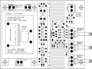
100W Hi Fi Amplifier Ras100 Version 2
Before “the new Hifi Amplifier Mosfet RAS300 RAS100 and PCB drawings” article for the RAS-100 100W MOSFET amplifier PCB shared drawing sketch I changed I said there’s no difference, but in fact the V2 have in terms of usability and pleasing to the eye to have had the opportunity to study the differences in performing the circuit does not have a problem also went smoothly, if I find an opportunity running post video to add. Added Ares version 7.0 files.
Stabilisierte geregelte Stromversorgung mit L200C 0.30V
Um das einfache Design der Stromversorgung und gleichzeitig einfache Ausgangsspannung und Stromgrenze zu erreichen, entschied ich mich, die bekannte monolithisch integrierte einstellbare Spannung und Stromregler L200-Serie im Fall Pentawat mit fünf Steckdosen von ST Microelectronics zu verwenden. Die Spannung kann auf die Werte von zwei externen Widerständen im Bereich von 2,75 V bis 36,0 V eingestellt werden, sofern die Eingangsversorgungsspannung mindestens 2,5 V höher ist. Ansonsten ist die maximale Eingangsspannung, die der Schaltung standhalten kann, 60 V. Im Vergleich zu anderen ähnlichen Schaltungen besteht auch weiterhin die Möglichkeit, einfach die Größe des Ausgangsstroms einzustellen. Wird diese Einstellung nicht verwendet, ist der Strom intern auf ca. 2A (3,6 A) begrenzt, bei idealer Kühlung. Abhängig von der Temperatur des Gehäuses ist es möglich, den Strom- oder Spannungsausgang auf niedrigere Werte zu begrenzen und Schäden am Stromkreis sowie seine thermische und Leistungsüberlastung zu vermeiden. Diese Schaltung ist sehr ähnlich zu einem Freund LM317T-Serie Stabilisator im Gehäuse TO220, aber im Gegensatz zu ihm, hat die Erfassung Eingangsstromgrenze (Pin 2 – Begrenzung), ähnlich wie im Fall UA723CN DIL14 gebracht. Die Schaltung befindet sich im Gehäuse PENTAWAT