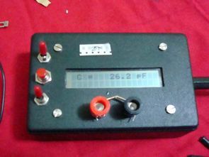
PIC16F84 LCD Display LC Meter circuit Box front waisted measure be careful when buying the box to cut the picture box paste it on top and falçata or drawing a knife then stop in the box bourdu to keep the four M3 screws and nuts, use Bordt USING the reader relays internal diode line is I’m a little late, I realized I did board relay leg reverse came first problem was that but in the scheme and BoardTM fix but I still protection diode I used the relay of different uses for kaldırmadım.pow source 12 Volt DC Jack (interior +) (outer portion of the Gnd)
I’ve used for testing terminal born request you make the connection, but the cable is too long to keep going to use.
Also I do jumper in a description:
J1: 16 × 1 LCD for those who want to use
J2: Frequency test
J3: Background light
Circuit Diagram, Box Size, Box Section, Box Cut Method
Contents


Box Cut, Cut Adapter Input, Internal Structure, PCB Bottom


PCB Top, Alignment, 2×16 LCD, Toggle Switch


Empty Test, Frequency Test, L Mode, 10μh Test


680μh test, 27pF SMD Test


LC Meter circuit eagle schematic pcb and hex code files
[wpdm_package id=’27321′]


Ultrasonic Cat & Dog Repeller Circuit PIC16F627
cat, dog repeller circuit’s all shared resources (asm hex + eagle pcb. Brd) Thanks to those who contributed People
NOTE: When programming the PIC16F627 internal oscillator fuse should be selected.