ATMEGA48 Many devices may be in standby mode during downtime. They do not perform any work, they are apparently disabled, but the control circuits are powered. To extract useful information from the point of view of working time, you should download it from the inside of the device, which may end up with a loss of warranty. ATMEGA48
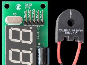
If the sensitivity of the system is too low then the resistance R15 can be increased. Otherwise, if the current in the transformer flows high current, the transformer itself must be adjusted to avoid damage. Used in the prototype ASM-010 is adapted to a maximum of 10 A.
The LM358 is undoubtedly inexpensive, but its disadvantage is its relatively high unbalance voltage, which can, in very unfavorable conditions, mask the sinusoidal input signal. If the changes described above do not work, you may consider using another operating amplifier, eg TLC277. It is important that its input stage properly handles the voltage close to zero.
Once done, the counter system is ready to go. Current consumption is approximately 11 … 15 mA, depending on the current content of the LED display. The power supply should be a constant voltage, well filtered and not necessarily stabilized, in the range of 8 … 30 V.
At the moment of power failure the stabilizer stops supplying the divider and the output of the comparator is set. This rising edge causes the interrupt handler to operate in which the display is turned off, and the current time indication is stored in the EEPROM. This solution does not overwhelm the EEPROM with regular writing, which is justified because the number of write cycles written to it is limited.
ATMEGA48 ASM-010 Schematic diagram
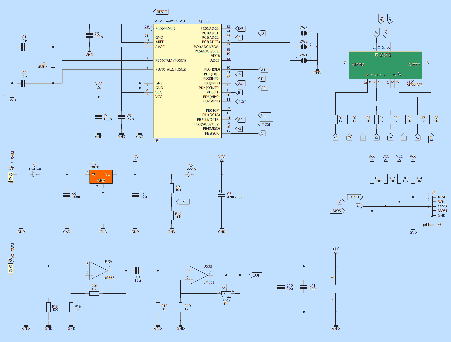
The work time clock schematic diagram The microcontroller used here is ATmega48PA. In this application, its great advantage is the ability to operate at a supply voltage of 1.8 V. This is critical when writing data to non-volatile EEPROM when the system is powered exclusively from the filter capacity. The frequency of the microcontroller clock generator is stabilized with a quartz resonator (4 MHz). The same generator is used to measure time.
The display has 4 digits, each with a common anode. Control of all leads is done directly from the microcontroller terminals because the current of the segments is limited to about 2.5 mA, so that the whole digit does not take more than 20 mA.
![]()
FILE DOWNLOAD LINK LIST (in TXT format): LINKS-25837.zip


ATMEGA48 Schaltuhr ausgelöst durch Stromfluss ASM010
ATMEGA48 Viele Geräte befinden sich möglicherweise während der Ausfallzeit im Standby-Modus. Sie führen keine Arbeit aus, sie sind anscheinend deaktiviert, aber die Steuerkreise werden mit Strom versorgt. Um nützliche Informationen aus der Sicht der Arbeitszeit zu erhalten, sollten Sie sie von der Innenseite des Geräts herunterladen, was zu einem Verlust der Garantie führen kann. ATMEGA48
Wenn die Empfindlichkeit des Systems zu niedrig ist, kann der Widerstand R15 erhöht werden. Andernfalls, wenn der Strom im Transformator hohen Strom führt, muss der Transformator selbst eingestellt werden, um Schäden zu vermeiden. Der im Prototyp verwendete ASM-010 ist auf maximal 10 A ausgelegt.
Der LM358 ist zweifellos preiswert, aber sein Nachteil ist seine relativ hohe Ungleichgewichtsspannung, die unter sehr ungünstigen Bedingungen das sinusförmige Eingangssignal maskieren kann. Wenn die oben beschriebenen Änderungen nicht funktionieren, können Sie einen anderen Operationsverstärker, z. B. TLC277, in Erwägung ziehen. Es ist wichtig, dass die Eingangsstufe die Spannung nahe bei Null behandelt.
Ist das erledigt, ist das Zählersystem bereit zu gehen. Der Stromverbrauch beträgt ca. 11 … 15 mA, abhängig vom aktuellen Inhalt der LED-Anzeige. Die Stromversorgung sollte eine konstante Spannung sein, gut gefiltert und nicht unbedingt stabilisiert, im Bereich von 8 … 30 V.
Im Moment des Stromausfalles hört der Stabilisator auf, den Teiler zu versorgen, und der Ausgang des Komparators wird eingestellt. Diese ansteigende Flanke bewirkt, dass der Interrupt-Handler arbeitet, in dem die Anzeige ausgeschaltet ist, und die Anzeige der aktuellen Zeit wird in dem EEPROM gespeichert. Diese Lösung überschreibt das EEPROM nicht mit normalem Schreiben, was gerechtfertigt ist, weil die Anzahl der geschriebenen Schreibzyklen begrenzt ist.