I have seen oscilloscope circuits working with a simple circuit over the sound card in many places, this circuit works over the lpt parallel port, the circuit consists of a simple ADC0820 and a few passive elements.
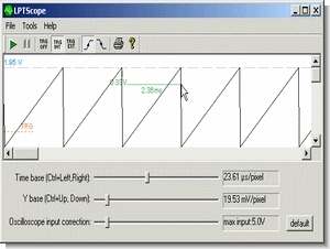
Windows program and source codes are given for measurement. Be careful while testing the circuit. Any mistake can damage the motherboard of your computer. You cannot measure high voltages with this circuit. There is a limit of around 2V.
Turn your computer into a free oscilloscope with the ADC0820 connected to the printer parallel port. In the beginning: I do not take any responsibility if you burn your PC or anything else. I don’t even care. You use this information at your own risk.
This oscilloscope uses the SPP or EPP parallel port (LPT1) to read data from the ADC. If your LPT1 is an ECP, the program will automatically switch LPT1 in byte mode (normal mode). BUT, not all parallel ports (LPT ports) are bidirectional. “Bidirectional” means that apart from data output, the port can also read data.
The test is carried out as follows:
1) The program sets pins 2-9 of the LPT1 port to fully high (5V). In other words: the program puts a 0xFF on the data port of your LPT1 at address 0x378
2) The program then continuously reads the LPT1 data port and monitors for any changes
3) Your task is to connect any data pin to ground. For example, connecting pin 2(DATA0) to pin 18(GND) changes the reading from 255 to 254. You must use a 1kOhm resistor to connect a “high” pin to the GND pin.
a) If the port is not bidirectional (pin 2 holds 5 volts), the 1k resistor is large enough to limit the current to 5mA. Sources 5mA from pin2 and sinks to pin18, this is acceptable on all ports without damaging pin18. (1kOhm means 5mA current at 5V).
b) If the port is bidirectional, the 1k resistance is low enough to pull pin 2 from 5 Volts to 0 Volts. (Except some notebooks. See Tips at the bottom of this page)
4) If the reading changes, that’s good news: your port is bidirectional!
If it doesn’t, try changing the settings in your PC’s BIOS first (in case your LPT1 is in MB). Try several times in the following order: Normal, EPP, or ECP.
If the test fails, you cannot use the above schematics. But hey, don’t give up. Just consider some other options. For example this . In this option, you have to greatly modify the above schematics and slightly modify the program in the LPT reading section. For example, this project uses multithreading. However, by using multiplex data collection, you get a sloppy, twice as slow read speed.
How to determine if your LPT1 port is bidirectional? Start the LPTscope program and select “Two-way aptitude test” in the program menu, and then follow the instructions provided.
Oscilloscope Circuits


Source: dosprinter.net Sound Card Oscilloscope Circuits ADC0820 alternative link:
Password: 320volt.com
Published: 2009/10/17 Tags: analog circuits projects
Voltage Regulator Calculator
Voltage Regulator Calculator program free electron calculator.. Easily available in the market now has become a classic for the positive regulator integrates a handy calculation, each integrated design program is displayed in the application circuit has in most current calculations in leveling
Voltage Regulator Desing Calculator