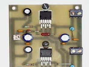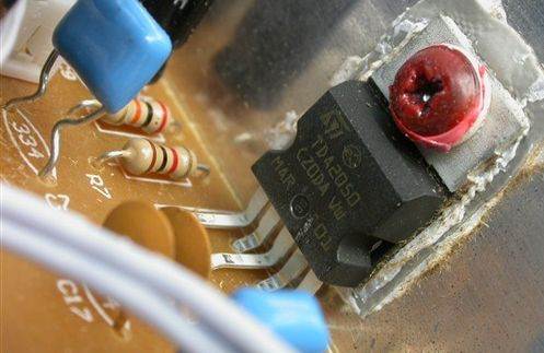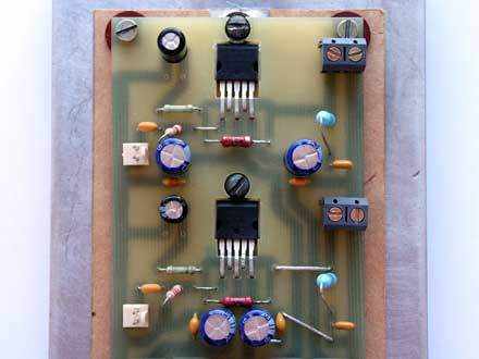
TDA2050 is used in the amplifier circuit, but if you want, you can use LM1875 or TDA2030 on the same pcb, the leg connections of these integrateds have the same power.
If 1875 is a maximum of 20 watts and 2030 is 18 watts, the AC voltage of the transformer you will use for these two integrated should be 13,13.v. It makes a lot of heat on the integrated integrated, all materials can be found in the market, a low cost simple amplifier circuit
You can use the free Sprint Layout Viewer< program to view the pcb drawing (.lay) of the amplifier prepared with Sprint layout and get print out. If the transformer to be used for the supply of the 32 Watt amplifier is 2x15 volt ac power, it should be at least 70w. You do not need to prepare an additional pcb for the supply circuit, rectifier bridge diode, filter capacitors, fuses, the appearance of TDA2050 integrated on a single pcb (others are the same)
The PCB design is very ideal for heatsink mounting, it is a good choice for people who do not want low-cost too much power. Do not forget to examine the datasheets of the ICs to determine the material and operating voltages according to the IC you will use.
TDA2050 Datasheet information
The TDA 2050 is a solid integrated circuit in a Pentawatt package, intended for use as an audio class AB audio amplifier. Thanks to its high power capability, the TDA2050 provides up to 35W of true rms power @ 4 ohm load @ THD = 10%, VS = ±18V, f = 1KHz and @THD = 10% power at 8 ohm load, up to 32W VS can provide = ±22V, f = 1KHz. In addition, the TDA 2050 typically delivers 50W of music power at VS= 22.5V, f=1KHz into a 4 ohm load in 1 second.
The LM1875 is a solid power amplifier offering very low distortion and high quality performance for consumer audio applications. The LM1875 delivers 20 watts into a 4 ohm or 8 ohm load on 25V supplies. Over 30 watts of power can be delivered using an 8 ohm load and 30V supplies.
The amplifier is designed to operate with minimal external components. Device overload protection consists of both internal current limit and thermal shutdown. The LM1875 design utilizes advanced circuit techniques and processing to achieve extremely low distortion levels even at high output power levels.
Other highlights include high gain, fast slew speed and a wide power bandwidth, large output voltage swing, high current capability and a very wide supply range. The amplifier is internally balanced and stable for gains of 10 or greater.
The TDA2030 is a solid integrated circuit in a Pentawatt® package, intended for use as a low frequency class AB amplifier. Typically provides 14W output power (d = 0.5%) at 14V/4W; At ±14V or 28V, the guaranteed output power is 12W at 4W load and 8W at 8W.
The TDA2030 provides high output current and has very low harmonic and crossover distortion. In addition, the device includes an original (and patented) short-circuit protection system with an arrangement that automatically limits the dissipated power to keep the operating point of the output transistors within the safe operating range. A conventional thermal shutdown system is also included.
source alex-jet.narod.ru TDA2050 32W amp pcb schematic alternative link:
Password: 320volt.com
Published: 2008/01/15 Tags: audio amplifier circuits, ic amplifier


PIC16F870 LMX2306 PLL FM Transmitter Circuit
FM PLL transmitter circuit 12V supply 500mW has the power circuit PIC16F870 and LMX2306 integrated based on the simple circuit of a single coil are killers though PLL (phase-locked loop-Phase-locked loop) circuits without line would sooner or later will deal though commercially available wound coils can be found
500mW FM PLL transmitter 88-108MHz
This is strictly an educational project explaining how a transmitter works and can be built. According to the law it is legal to build them, but not to use them. This transmitter is PLL controlled and the frequency is very stable and can be programmed digitally. The transmitter will work from 88 to 108 MHz and the output power is up to 500mW. With minor changes the frequency can be set from 50 to 150 MHz.
TDA2050 Verstärkerschaltung in der gleichen Platine verwendet, aber wenn Sie möchten, können Sie die LM1875 oder TDA2030A verwenden, um diese verschiedenen Beine der gleichen Stromanschlüsse zu integrieren. lm1875 werden für diese beiden integrierten Wechselspannungswandler 13.13 maximal 20 Watt und 2030 18 Watt verbraucht. Hätte mehr tun sollen, um all die Wärme auf kostengünstigen Materialien zu integrieren, die in piayasa zu finden sind. Eine einfache Leiterplattenzeichnung des Verstärkers (.Layer) für die Sprint-Layout-Ansicht und die kostenlose Druckausgabe, um mit dem Sprint Layout Viewer vorbereitet zu werden