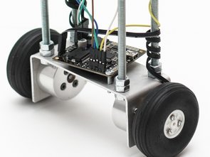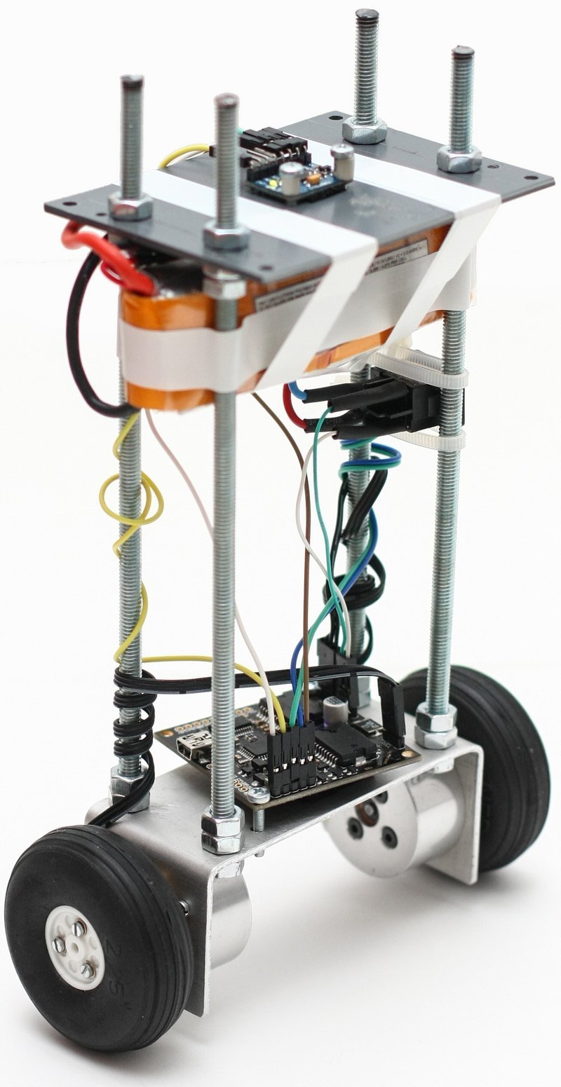
ATmega328, BLDC Motor, Gyroscope, accelerometer, inverse pendulum, I2C bus, Martinez V3, controller, modeling simulation, Matlab, Simulink, MPU6050 This work deals with the construction of two-wheeled mobile robot and subsequent creation drivers and controls for its sensors, motors and controller design. Management works on Arduino platform with ATmega328 processor. In the first place, the research is carried out.
The part of the thesis is a model part, where the simulation model of the system is created, its
linearization and subsequent controller design. It also contains a description of the production and construction of the robot body, description and functionality of used motors, description of all sensors and sensors and detailed description supplied PCBs. And finally, the program part where control is discussed motors, working with sensors and controller functionality. The result of this work is a functional application control and control of a two-wheeled unstable robot.
The two-wheeled mobile robot, whose center of gravity is above the wheel axis, behaves like an inverse pendulum that we see as a generally unstable system. Stabilizing such the system is achieved by maintaining a mechanical equilibrium, a condition in which the body’s axis is robot perpendicular to Earth’s acceleration.

A differential type chassis is used as a chassis for two-wheel robots. The differential chassis is based on two independently driven wheels. So the robot is capable of straightforward forward and backward movement, oblique motion, and rotation in place. The advantage is good maneuverability and simple, relatively accurate odometry. The disadvantage is poor terrain resistance. When performing any movement, the robot is kept stable. That’s it an old microprocessor with control elements using a combination of gyroscope and accelerometer. The microprocessor processes the data from the accelerometer and gyroscope and transmits it to the designed one controller, which in turn, by means of two bridges, controls the operation of both motors respectively kol. To create a controller, it is necessary to identify the system and then design it regulator. The system identification will be done using Lagrange equations II. kinds. Because of the physical nature of the problem, the main requirements for regulation are primarily regulation speed and overshoot size. The role of control and control of differential chassis or double wheel
A mobile robot is a frequent topic not only at the academic level but also at the level commercial and also amateurs. The reason for the great popularity of this task is the use of a wide one spectrum of fields of automation. And from the processing of data from sensors through control using microprocessors, design of printed circuit boards and power elements up to motor control itself. It can also include wireless control via PC and computer program.
This work will concern the mobile robot control system. The aim of the work is construction robot, installing available sensors, motors and PCBs. Choosing a suitable power element and overall recovery of all parts. Furthermore, sensors for reading sensors, regulation will be created and motor control. The main goal is to achieve a state where the robot will be able to stand alone upright without external action.
Mobile Robot Circuit Schematic
FILE DOWNLOAD LINK LIST (in TXT format): LINKS-26219.zip
Published: 2019/07/16 Tags: avr project, microcontroller projects

Adjustable Switch Mode Power Supply 0.25V 0.5A TL494
Adjustable Switch Mode Power Supply 0.25V 0.5A TL494
Switch Mode DC DC Adjustable Power Supply The TL494 system is the heart of the stabilizer. Elements C13-1.5NF, R14-10K set the frequency of the internal generator work to about 77 kHz. Comparator first, along with elements R7, R8, R9, R15, R16 and C14 are the output voltage stabilization circuit, which the value is regulated by the potentiometer P2. Comparator second with elements R10, R11, R12, R21 and R22 they constitute the current regulator circuit, whose value is set with potentiometer P1. The POW connector enables power supply of the control block and power block with the same voltage (1-2 shorted), or enables power supply control block from an external source, we attach them to pins 2-3, (2-plus, 3-mass).
This voltage should be in the range of 8 … 40 VDC. The CTRL connector allows switching off the stabilizer by providing a voltage of approx. 5 V on pin 2. The connector VALUE is used for regulation potentiometers as in the diagram. Elements T1 BDW84C, D1 F16C20 or BYW29, L1 and C5 form a typical impulse “step-down” converter. The other elements filter the input and output voltages. Lower range current regulation (0 … 0.5A) is difficult to obtain, therefore the scope of practical adjustment is … 0.5A 5A.
• 0 … 25V output voltage
• current limitation 0 … 5A (0.5A … 5A)
• smooth regulation of voltage and current
• possibility of remote switching off the stabilizer
• power supply: 24VAC or 2x24VAC
Projet de robot mobile MPU6050 ATmega328
ATmega328, moteur BLDC, gyroscope, accéléromètre, pendule inverse, bus I2C, Martinez V3, contrôleur, simulation de modélisation, Matlab, Simulink, MPU6050 Ce travail traite de la construction d’un robot mobile à deux roues et des pilotes de création et des commandes subséquentes pour ses capteurs, conception des moteurs et des contrôleurs. La gestion fonctionne sur la plate-forme Arduino avec le processeur ATmega328. En premier lieu, la recherche est effectuée.