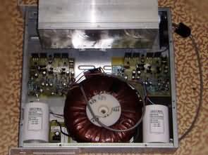
2X200W transistor amplifier circuit The aim of this bachelor thesis was to design a low frequency power amplifier for speakers for the purpose of sound public events. Its use therefore determine addressed the concerns of the processing, where required by the supply of sufficient power (at least 200W per channel into a load of 4Ω) for four odposluchy serving musicians, DJ, bands, singers and others. His proposal demanded high-quality processing, as the custom filing sound for the musician it must be sufficiently loyal and quality, so that it could assess whether to improve. This work addresses the complete involvement of of the amplifier and thus contains the analysis of the individual blocks as they are the ac power source, the preamplifier, the amplifier stages but also the module spds speakers and amplifier.
2X200W Amplifier Schematic

Estimated parameters of the amplifier The amplifier is designed to be minimized by TIM. In emitoroch input difference degrees are resistors the resistance of 300Ohm and the bandwidth of the amplifier with an open loop feedback is adapted capacitors C22 and C23 in the rozkmitovom stage and capacitor C29 in a feedback between the entering. The amplifier has a theoretical the performance of at least 200W into 4 ohms, harmonic distortion of typically 0,01%, the units of production bandwidth around the 8.5 MHz and the speed of the 60V/µs.


![]() 2X200W Amp circuit pcb schematic all files alternative links:
2X200W Amp circuit pcb schematic all files alternative links:
FILE DOWNLOAD LINK LIST (in TXT format): LINKS-25700.zip
Published: 2016/06/19 Tags: audio amplifier circuits, transistor amplifier
Switchmode Lead–acid Battery Charger UC3845 SMPS 12V 6V 50A
UC3845 Lead–acid Battery SMPS Charger The board is designed as a superior power and a subordinate current regulation, which is powered from the main board. Voltage is sensed using a voltage divider directly on the output switching power supply. Current is sensed by current transformer TR2
and further streamed diode D20, and subsequently converted into voltage insulators on the
voltage. Using a 3-pole switch, you can choose the size of the voltage regulation. Whereupon the position of the the left corresponds to the value of 7.2 V for battery motorcycle batteries with nominal voltage of 6V and position to the right corresponds to the value of 14.4 V for battery cars by nominal the value of 12V.
2X200W RMS Verstärker Schaltung MJL21196 MJL21195
2X200W transistor Verstärker Schaltung Das Ziel dieser Bachelorarbeit war die Entwicklung einer niedrig-Frequenz Endverstärker für Lautsprecher für die Zwecke der Klang öffentlichen Veranstaltungen. Seine Verwendung bestimmen somit adressiert die Bedenken der Verarbeitung, wo erforderlich, durch die Zufuhr von ausreichend Energie (mindestens 200W pro Kanal an einer Impedanz von 4 Ω) für vier odposluchy portion Musiker, DJ, bands, Sänger und andere. Sein Vorschlag verlangt hochwertige Verarbeitung, wie die benutzerdefinierte Ablage-sound für die Musiker muss es ausreichend loyal und Qualität, so dass er einschätzen konnte, ob sich zu verbessern. Diese Arbeit behandelt das komplette Einbindung des Verstärkers und damit enthält die Analyse der einzelnen Bausteine, wie Sie die ac-Stromquelle, dem Vorverstärker, dem Verstärker Stadien, aber auch das Modul spds Lautsprecher und Verstärker.