In the timer circuit, there are buzzer and audible warning section and relay outputs for control after timing. The supply voltage is 12 volts dc. It is fed through the PIC16F84A 7805 Regulator IC. Second and minute settings can be made. Most likely, the specified times can be changed via asm code. Timer a timer b can be selected.
Programmable Flexible timer
It is easy to create, program and can be set to give consecutive time periods of up to 99 minutes and 59 seconds. What’s more, you can program up to 99 time zones.
ELECTRONIC TIMERS have always been popular. In fact, there are enough applications for this type of project to scratch the surface just to mention: parking meter reminders, EPROM erase timing, darkroom printer/enlarger timing, battery charge timing, industrial operation timing, chess and other board game timing, discussion timing and even kitchen timing.
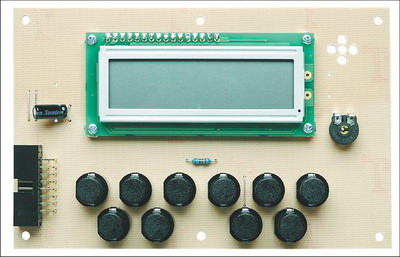
The circuit is based on a programmed PIC16F84A microprocessor, which drives an LCD module, two relay driver circuits (one for Time A and one for Time B), and a piezo buzzer circuit. It is programmed using 10 button switches.
If you want to make a timer with the widest application range, it must have at least two independently adjustable or “programmable” timing periods. Ideally, it should also be flexible in terms of the number of time periods and/or time period sequences (or loops) that can be programmed.
Some applications need only one time period, timed “one shot”, while others need a single time period followed by a second (and possibly different) time period. Still other applications may need two sequences of time slots repeated many times for a total of 20 cycles.
The multifunctional timer circuit is programmed in the same intuitive way as a microwave oven. First, it has a tens and unit button that lets you enter the exact number of minutes and seconds for the time period(s) you want, as well as the number of timings you want. Manually starting and stopping the timer and changing its settings the next time you use it etc. There are also buttons to save.
PIC16F84A Timer Circuit

Source: http://www.siliconchip.com.au/cms/A_105013/article.html
Programmable Timer Circuit PCB schematic PIC16F84A pic assembly source code alternative link:
Password: 320volt.com
Published: 2008/09/02 Tags: microchip projects, microcontroller projects, pic16f84 projects
PIC16F88 12V SLA Battery Charger Circuit
PIC16F88 microcontroller used in the circuit description, circuit diagram, pcb asm hex code file there. Able to deliver 60 amps to 10 amps charging current used to charge the batteries temperature control with LED display and so on. includes features such as.
SLA Battery Charger Circuit