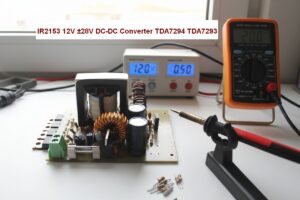
DC to DC converter circuit 12 volt input 15 volt 2 amp converter circuit MC34063 output power raises Step-Up-Down and Inverting can function as integrated switching is used.
DC / DC converter circuit general characteristics;
Input voltage: 10. 14volt
Output voltage: 15 volts, 2 amps
Yield: 80%
0.8mm wire coils used in the circuit 30 to be wound round the core output filter used in computer power supply 5w R1 Resistance 0.1Ω
The converter is intended for powering 3 cell chargers of Li-Ion and Li-Pol cells as well as gel PB from a car battery. The voltage of the lead-acid battery is not enough to fully charge the three cells to the maximum. It is therefore necessary to use converters to increase the voltage. Several instructions for the inverter have already been published, this one should be cheap while maintaining simplicity.
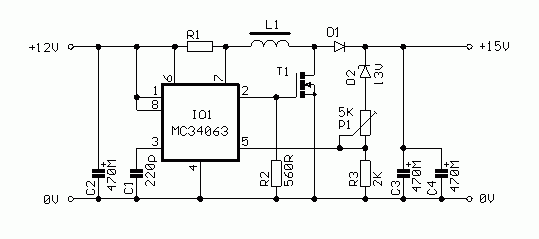
This is a very common connection of a step-up converter with a choke. The basis of the entire inverter is the MC34063 integrated circuit. Although this type is not as good as Maxim circuits, the main reason for its use is the very low price.
The circuit is connected quite standardly in the catalog connection. The output of the circuit is amplified by a Mosfet transistor. The basic operating frequency of the inverter is set by capacitor C1. The output voltage is determined by a voltage divider on terminal No. 5, which reduces the output voltage to the reference voltage level of 1.25V. Diode D2 is used to reduce output voltage ripple. Using P1, the output voltage can be set in the range of about 14-16V. Resistor R1 is a current shunt to limit the output current. It must be rated for the maximum current from the source.
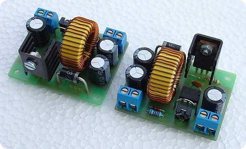
The inverter is on a single-sided printed circuit board. We assemble gradually from the smallest components to the largest. There is one wire jumper on the board at T1. We connect diode D1 approx. 10-15 mm above the board, because its terminals are also used for cooling. Transistor T1 is equipped with a small heatsink. Resistor R1 is made of kanthal resistance wire with a diameter of 0.8 mm. We clean the 30 mm wire at both ends and tin it to a length of 4 mm. We then connect the loop to the board. The connection must be of good quality so that transitional supports do not arise. It is advisable to glue the choke to the board with epoxy. glue.
The board is designed universally for possible experiments with increasing the power of the inverter. It involves the use of a power diode in a TO220 case and a drive circuit of a power transistor.
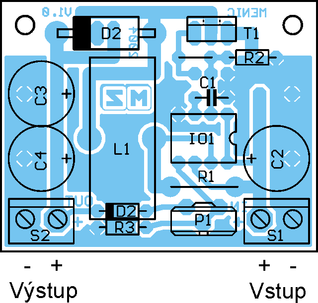
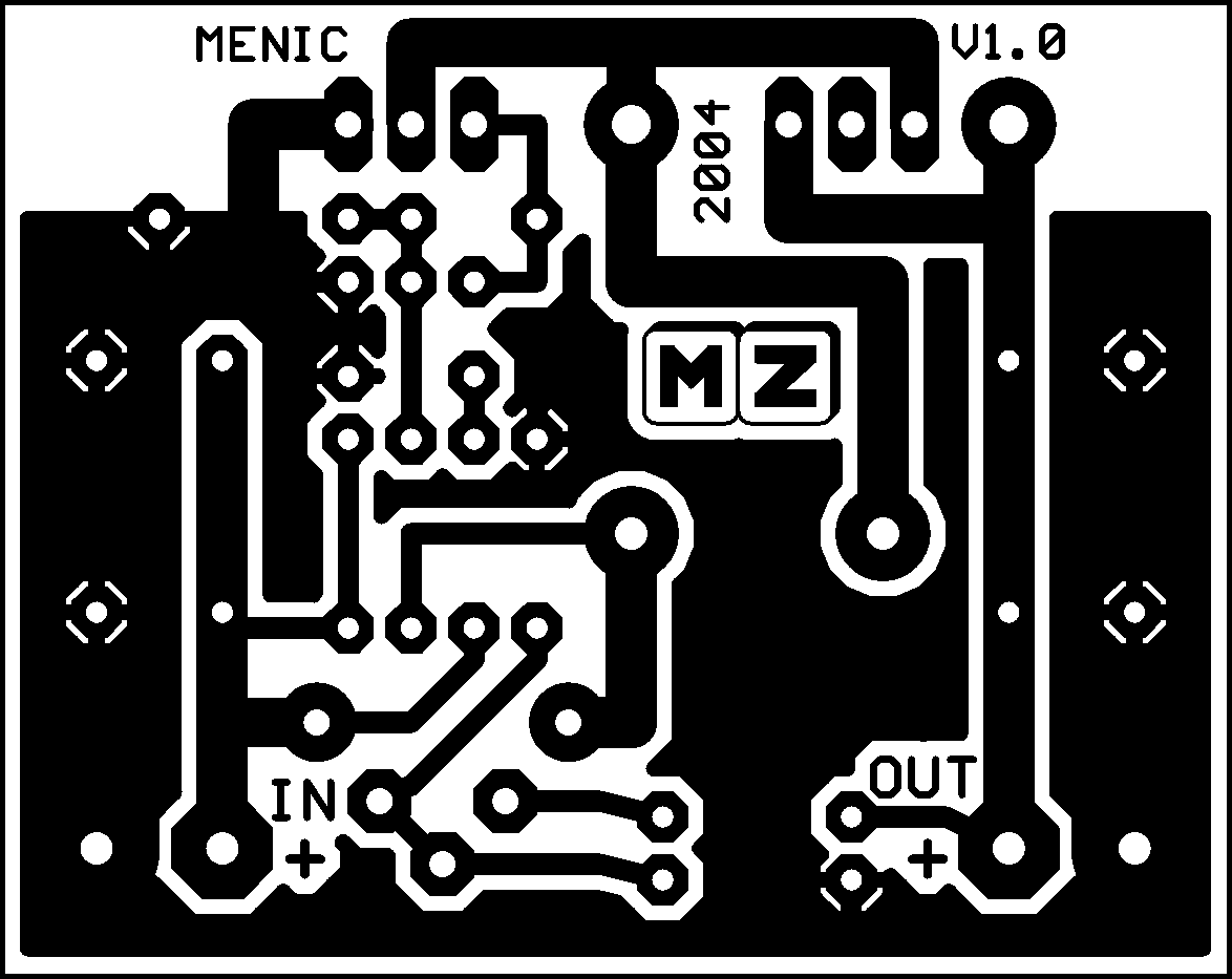
Assembly drawing and printed circuit board (size 50 x 40 mm, 600dpi)
Parts list:
R1 – resistance wire, see text.
R2 – 560R
R3 – 2K0
P1 – 5K0 trimmer
C1 – 220pF ceram.
C2,3,4 – 470M/25V
D1 – SB360
D2 – BZX83V013
T1- BUZ71
IO1 – MC34063 (PV34063)
L1 – DPU068A3
Cooler DO1A, terminals
We will perform a visual inspection of the entire board. Then we connect the inverter without load to a stabilized laboratory source and gradually increase the voltage from 0 to 12V while constantly checking the current. If there is already a large current draw at a low voltage, there is a gross defect in the connection and it must be removed. Otherwise, from about 8V, the inverter kicks in and the empty consumption is up to 20 mA. We set the output voltage to approx. 14.5 to 15V and we can test the converter under load and powered from the accumulator. It is necessary to realize that when testing the power from the source, the source must be able to give a significantly larger impulse current than the average taken. Therefore, if we want to test the inverter at full power, it is necessary that the power supply is able to provide at least 5A. The current limitation should work at a current of approx. 2.3A and more. When the inverter is operating at full power, all power components R1 heat up,
When used with the MZ charger ( RCR9/2002 ), it is necessary that when setting the voltage of the charger module, this charger is not powered from the inverter, but from a stabilized source, as described in the manual. High-frequency ripple in the output voltage can affect the accuracy of the setting.
Source: zajic.cz 12V to 15V DC DC Converter Circuit pcb sch Alternative link:


Ferrite Core Calculator Programs Core Design Tools
Nüve Ferit Hesapmala Programları – Power Factor Correction (PFC) ,AC Reactor (ACR),Common Mode Choke (CMC) Core,DC Choke (DCC) Core,Normal Mode Choker (NMC) Core,MAGAMP magnetic amplifier cor,Output Inductor (OI) Core Design Tool Programlar üçretsiz Bedavadır
DC / DC-Wandlerschaltung 12-Volt-Eingang 15-Volt-2-Ampere-Wandlerschaltung Der MC34063 erhöht die Ausgangsleistung, und die Invertierung kann als integrierte Schaltung verwendet werden.
Allgemeine Eigenschaften der DC / DC-Wandlerschaltung;
Eingangsspannung: 10. 14 Volt
Ausgangsspannung: 15 Volt, 2 Ampere
Ausbeute: 80%
0,8 mm Drahtspulen, die in der Schaltung 30 verwendet werden, werden um das Kernausgangsfilter gewickelt, das in der Computerstromversorgung 5 W R1 verwendet wird. Widerstand 0,1 Ω