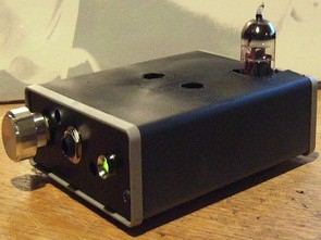
The sound quality is pretty good I guess. The lamp used is 12AU7 Mosfet irf612 circuit, not too complicated. The supply is 12volt dc. As a follower of several YAHA amps based on the Fa-schmidt design and a Szekeres Mosfet, I wondered how the two would sound together.
So I installed the schematic in TINA-TI, a free program for testing circuits before construction, and the results were remarkable. Approx 20dB gain from 13VDC power supply from 20Hz-100kHz.
As you can see in the diagram, there are less than 30 individual components and most DIYers will get them as spares from other builds.
I chose the 12AU7 / ECC82 vacuum tube because it can be operated with low voltage and the filament voltage is 12.6 volts, so there is no need to regulate the voltage further. I used a 1/4W resistor in the first stage and a 2W resistor in the second stage.
2W resistors may be too much, but I didn’t want to change them later. The 20ohm resistor should be a minimum of 5W and do not use cable wrap as the inductive properties will distort the response curve.


source diyaudioprojects.com
Published: 2008/11/08 Tags: audio amplifier circuits, transistor amplifier
PIC18F8722 CCS C TEF6901AH GPS Traffic Info
GPS is difficult to apply a great resource on a project can be difficult to find parts, but sources in our country ccs codes may work for you or pic18f8722 circuit diagram Nokia 6610 LCD (GLCD 128 × 128) gives an idea about the use of rides